Laser slit lamp with laser radiation source

a laser radiation source and laser slit lamp technology, applied in the field of ophthalmology, can solve the problems of high setup cost, high number of electric connection lines between the laser radiation source and the applying system, and substantial disadvantages of known combinations of external lasers and slit lamps

Inactive Publication Date: 2005-03-29
CARL ZEISS SMT GMBH
View PDF10 Cites 13 Cited by
  • Summary
  • Abstract
  • Description
  • Claims
  • Application Information

AI Technical Summary

Benefits of technology

to provide a laser slit lamp which extensively overcomes the disadvantages of the prior art and which provid

Problems solved by technology

The extensive space requirement for the external laser source and the beam losses occurring on the path from the radiation source, via the slit lamp with the applicator, to the eye of the patent have proven to be substantial disadvantages in known combinations of external lasers

Method used


Image

  • Laser slit lamp with laser radiation source
  • Laser slit lamp with laser radiation source
  • Laser slit lamp with laser radiation source

Examples


Embodiment Construction

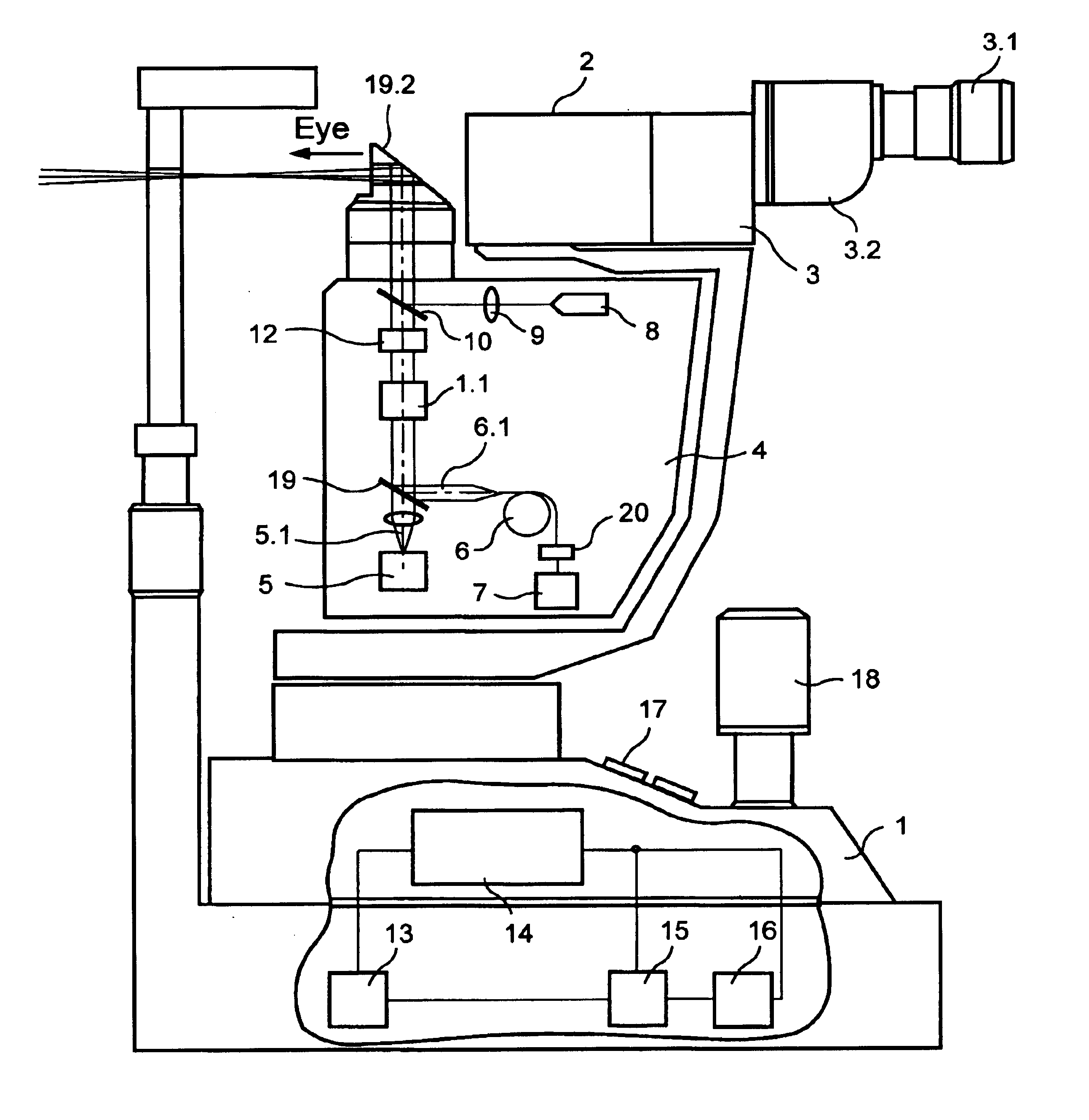
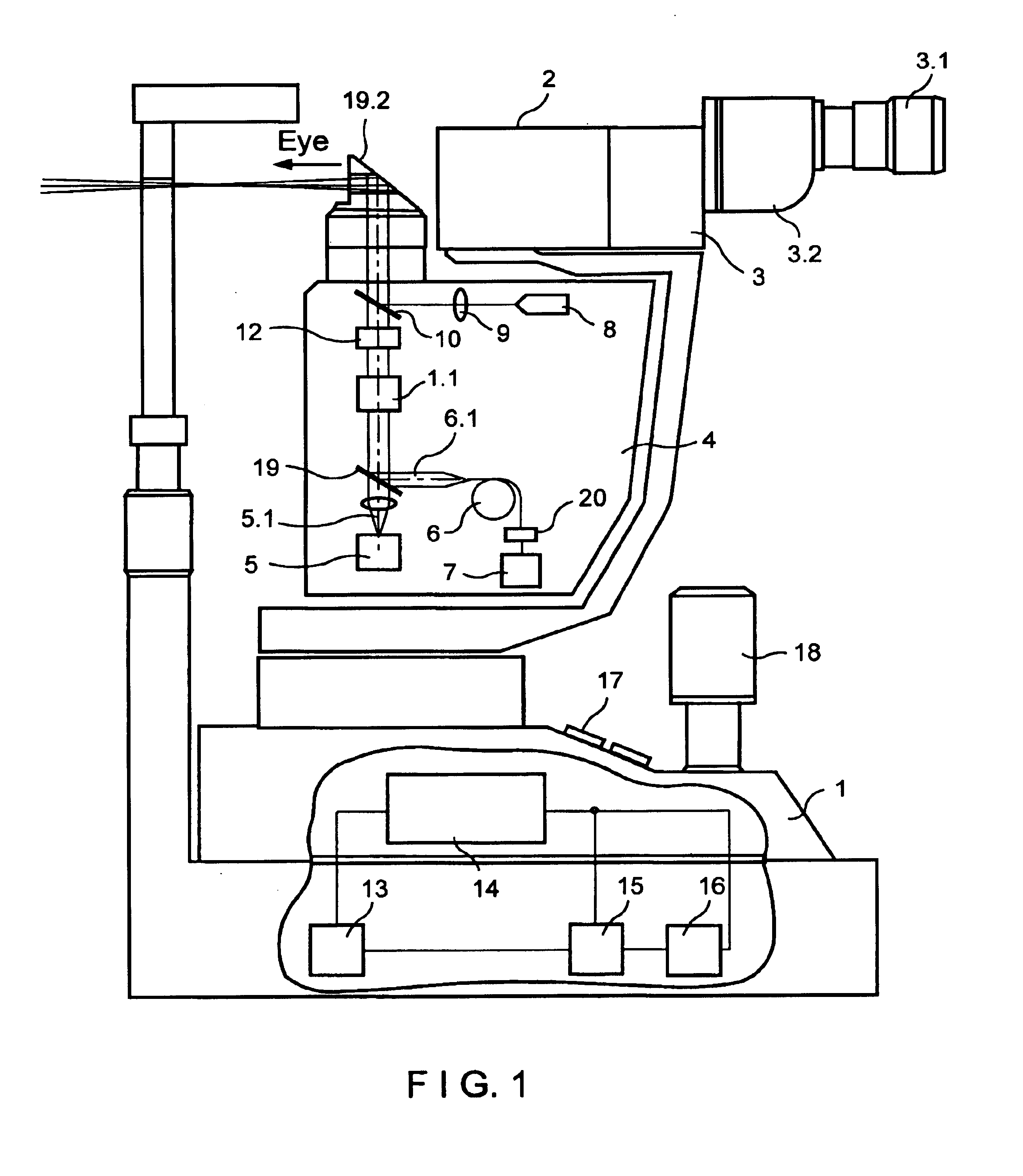
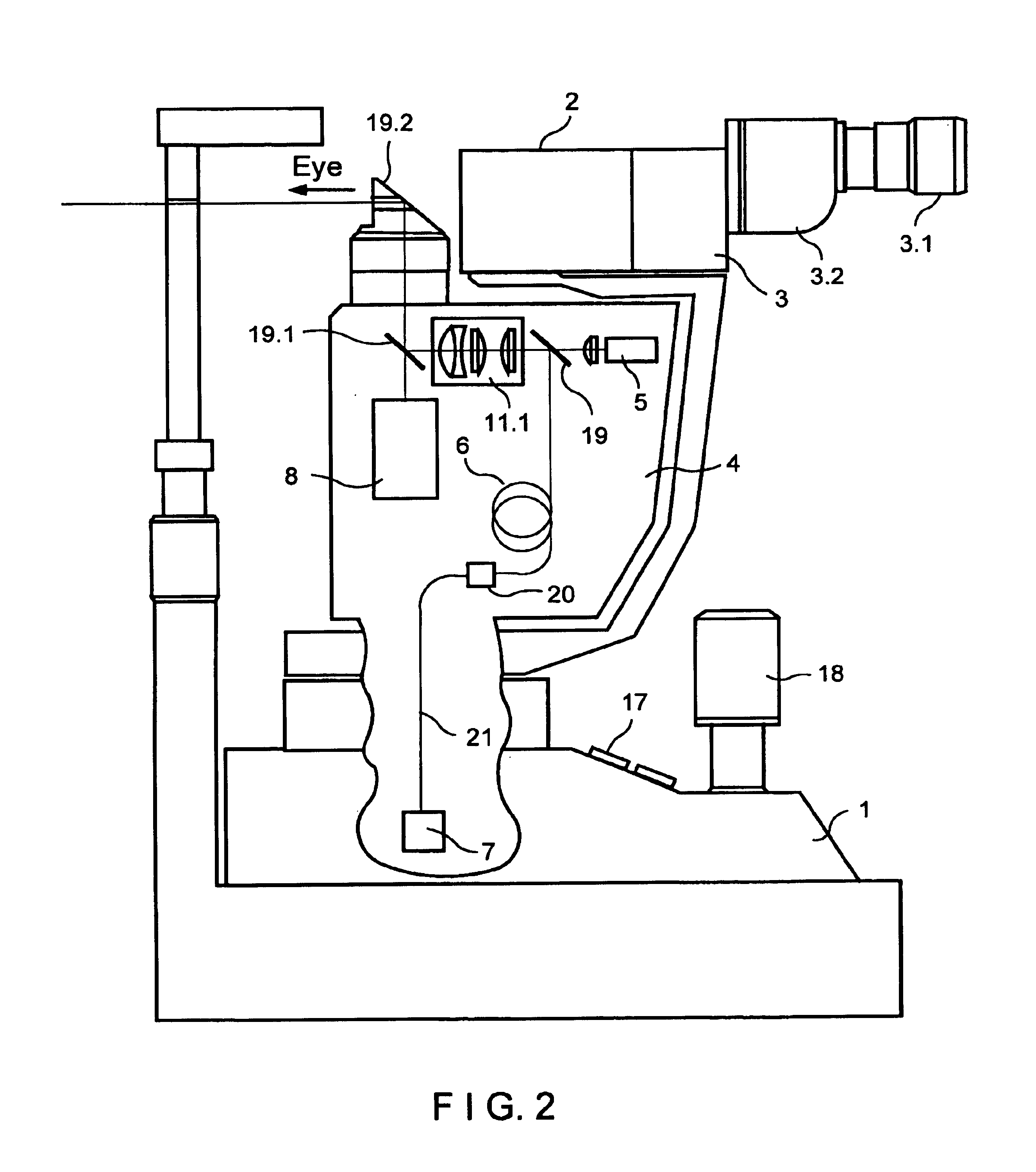
The laser slit lamp according to the invention which is shown in a simplified manner in FIG. 1 comprises a slit lamp base 1, a slit lamp head 2 and a slit lamp microscope 3 with eyepiece 3.1 and tube 3.2 for observing the eye to be treated and the area or point in or on the eye to be treated. An applicator 4 having means for uniting radiation from different radiation sources collinearly is connected to the slit lamp. These radiation sources can be marking or target radiation sources 5 which supply a target beam or marking beam 5.1 or a working radiation source 6 which generates a treatment beam or working beam 6.1 and which is shown in FIG. 1 as a fiber laser. A radiation source 7 generating the pump radiation is arranged in the applicator 4 in this arrangement for generating the laser radiation source used for operation as working radiation source 6. In the slit lamp according to FIG. 4, all other radiation sources are also arranged in the applicator 4.

An illumination radiation sou...


PUM


Abstract

A laser slit lamp comprising a slit lamp base, a slit lamp head and a slit lamp microscope. The laser slit lamp is connected with an applicator. It comprises a device for uniting radiation from at least two radiation sources collinearly and for directing the radiation of a treatment beam or working beam onto the location to be treated in or on the eye of a patient, a device for generating a target beam or marking beam for targeting and observing the location to be treated in or on the eye, and an adjusting device in the applicator for changing the intensity and diameter of the working beam spot used for treatment. The radiation sources are laser radiation sources arranged in the slit lamp head, in the slit lamp base or in the slit lamp microscope for generating the working beam, illumination beam and/or target beam. Devices for control, regulation and monitoring are likewise arranged in the interior of the slit lamp.

Description

CROSS-REFERENCE TO RELATED APPLICATIONSThis application claims priority of German application No. 101 00 857.0, filed Jan. 11, 2001, the complete disclosure of which is hereby incorporated by reference.BACKGROUND OF THE INVENTIONa) Field of the InventionThe invention is directed to a laser slit lamp with a laser radiation source and relates to the field of ophthalmology for diagnostic and therapeutic applications. Slit lamps with laser applicators are used in this field particularly for treatments of the retina such as panretinal photocoagulation in diabetic retinopathy, retinal welding in retinal detachment, grid coagulation of the retina in age-related macular degeneration (AMD) and for glaucoma treatments, e.g., trabeculoplasty in chronic glaucoma or iridotomy in acute glaucoma.b) Description of the Related ArtSpecial laser slit lamps or diagnostic slit lamps with special link systems or applicators from many different manufacturers which are connected by a light-conducting fiber...

Claims


Application Information

Patent Timeline
IPC IPC(8): A61B3/135A61B3/13A61F9/008A61F9/007G02B21/06A61B18/20
CPCA61B3/135A61F9/008A61F9/00821G02B21/06A61F2009/00863A61F2009/00891A61F9/009
Inventor GERLACH, MARIOWIECHMANN, MARTINKITTELMANN, OLAFZIMARE, DIEGOKEMPE, MICHAELMUEHLHOFF, DIRKKALIES, ALEXANDER
Owner CARL ZEISS SMT GMBH
Why Eureka
Try Eureka