Over-the-wire interlock attachment/detachment mechanism

a technology of over-the-wire interlocking and attachment mechanism, which is applied in the field of over-the-wire interlocking attachment/detachment mechanism, can solve the problems of difficult to advance over a medical implant device, require skilled manipulation, and be particularly difficult to remove medical implants from the hear

Inactive Publication Date: 2005-08-30
WL GORE & ASSOC INC
View PDF39 Cites 406 Cited by
  • Summary
  • Abstract
  • Description
  • Claims
  • Application Information

AI Technical Summary

Benefits of technology

[0010]A further object to the present invention is to provide a novel and improved over-the-wire interlock attachment / detachment mechanism well adapted for use with over-the-wire implanted medical devices.
[0012]A further object of the present invention is to provide a novel and improved over-the-wire interlock attachment / detachment mechanism which includes no overlapping components and which maintains a low profile configuration during passage through a vessel and / or catheter.

Problems solved by technology

The problem with known snare recovery devices is that they are difficult to advance over a medical implant device and require skilled manipulation to retrieve an implanted device.
It is particularly difficult to remove medical implants from the heart, such as septal occluders, with known snare recovery devices.
Such snare recovery devices normally require appropriate sizing to the vasculature in order to facilitate successful ensnarement, and the geometry of multi loop snares is difficult to maintain during delivery.
The relative position of the loops can change, both within a catheter or delivery tube and within a vessel, and the loops can actually become displaced or entangled during delivery.

Method used


Image

  • Over-the-wire interlock attachment/detachment mechanism
  • Over-the-wire interlock attachment/detachment mechanism
  • Over-the-wire interlock attachment/detachment mechanism

Examples


Embodiment Construction

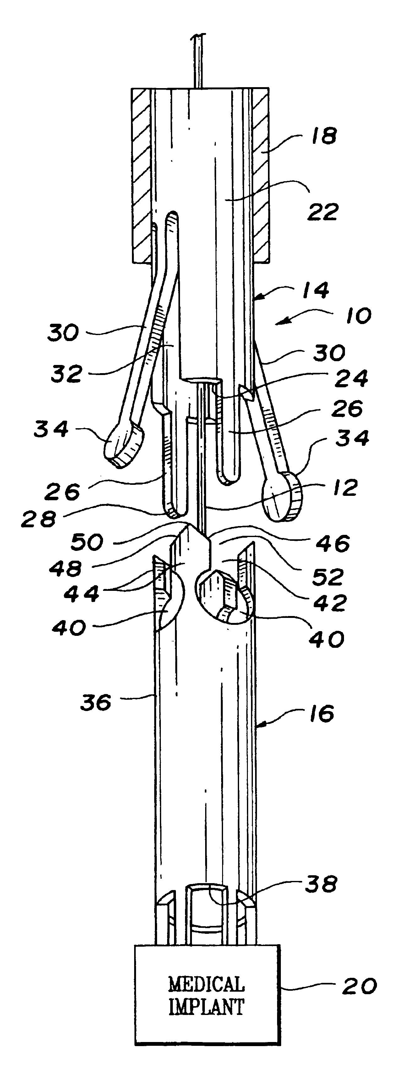
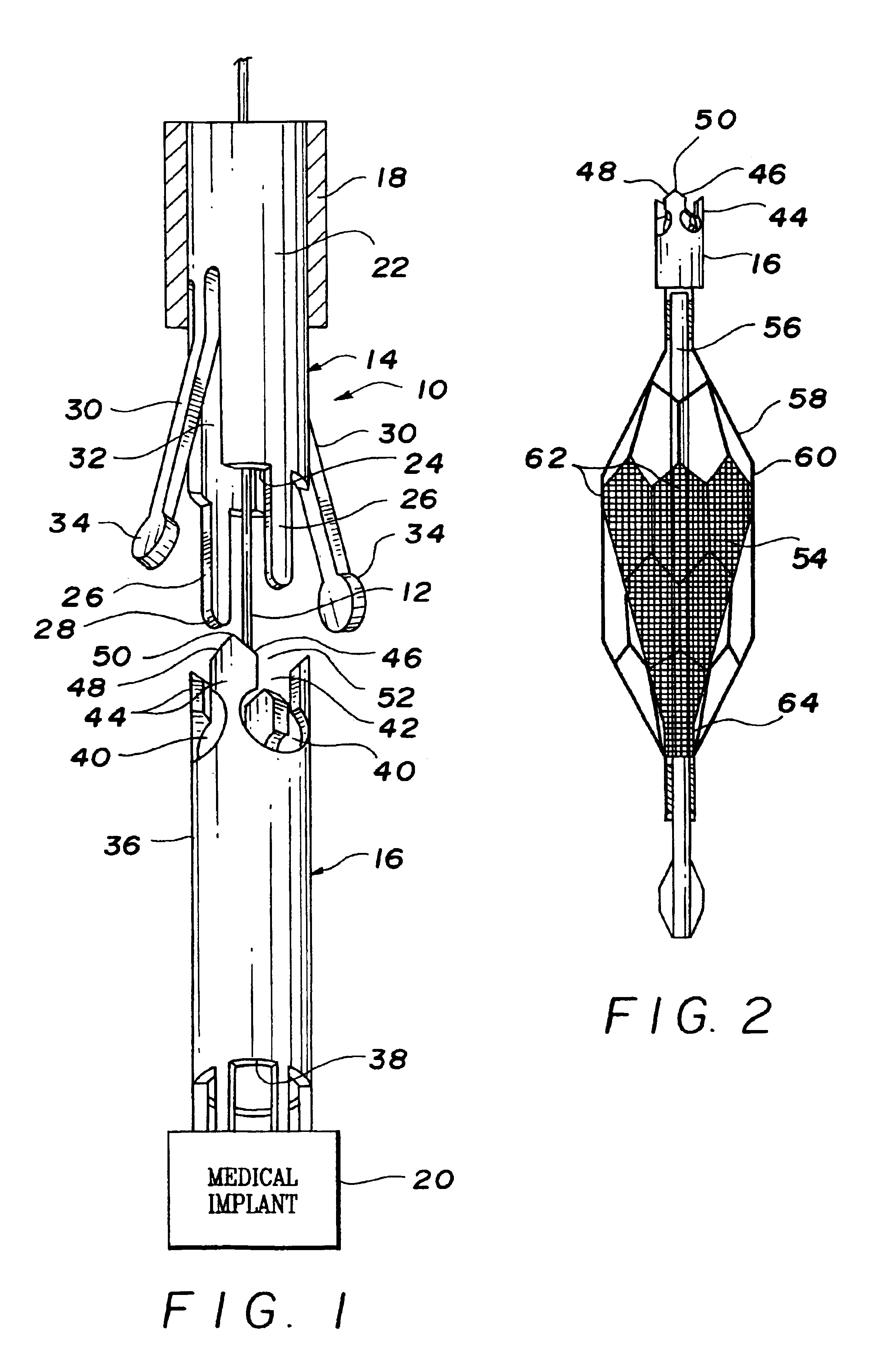
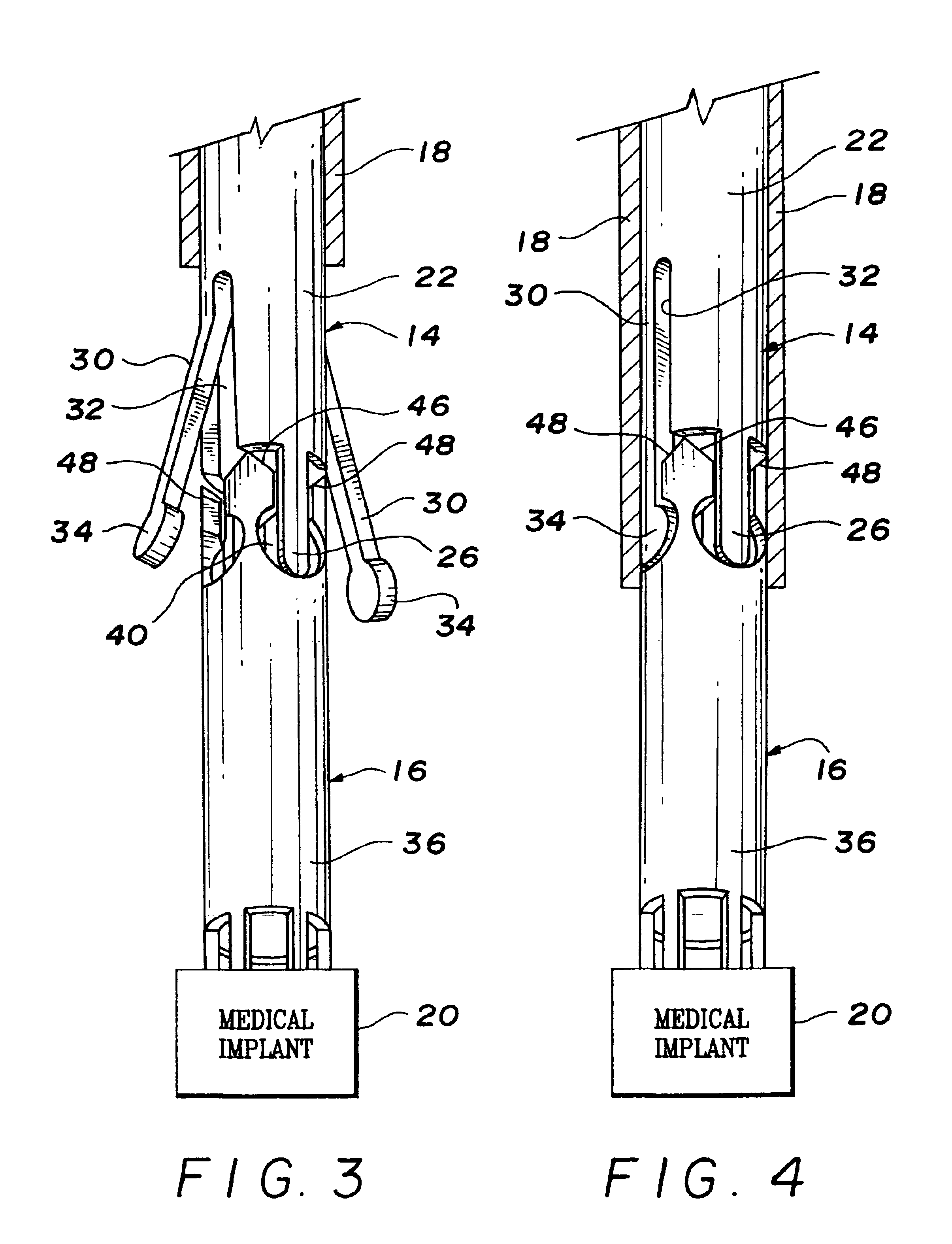
[0020]Referring to FIG. 1, the over-the-wire interlock attachment / detachment mechanism of the present invention indicated generally at 10 is adapted for movement along a conventional guidewire 12 such as a 0.014″ guidewire. The over-the-wire interlock attachment / detachment mechanism includes a male locking section 14, a female lock receiving section 16, and a tubular sheath 18 dimensioned to slide over the male and female sections. Preferably, the female section 16 is secured to an implantable medical device 20 such as a septal occluder, a filter or stent to be released in the heart or a blood vessel or other vessel of the human body or to be retrieved or repositioned within the heart or vessel.

[0021]The male locking section 14 includes a tubular body 22 which defines an open ended central chamber 24 through which the guidewire 12 passes. Projecting outwardly from the forward end of the tubular body 22 are one or more elongate guide fingers 26. These guide fingers are straight, elon...


PUM


Abstract

The over-the-wire interlock attachment / detachment mechanism includes a cylindrical lock receiving section of a small diameter attached to an implantable medical device such as a blood clot filter, a stent, or a septal occluder. This cylindrical lock receiving section has a plurality of spaced, curved cutouts to receive both the guide fingers and contoured locking fingers formed on a cylindrical locking section. The locking fingers are angled outwardly from the cylindrical body of the cylindrical locking section, and are moved inwardly into engagement with the curved cutouts of the cylindrical lock receiving section by a sheath which slides over the cylindrical locking section or other suitable operator.

Description

[0001]This application claims the benefit of provisional patent application Ser. No. 60 / 241,005 filed Oct. 18, 2000.BACKGROUND OF THE INVENTION[0002]In recent years, a number of medical devices have been designed which are adapted for compression into a small size to facilitate introduction into the heart or a vascular passageway and which are subsequently expandable. These devices, among others, include septal occluders, stents and free standing filters which expand and are held in position by engagement with the wall of an organ or vessel. It has been found to be advantageous to form such devices of a shape memory material having a first, relatively pliable low temperature condition and a second, relatively rigid high-temperature condition. By forming such devices of temperature responsive material, the device in a flexible and reduced stress state may be compressed to fit within the bore of a delivery catheter when exposed to a temperature below a predetermined transition tempera...

Claims


Application Information

Patent Timeline
Patent Type & Authority Patents(United States)
IPC IPC(8): A61F2/06A61F2/01A61B17/12A61B17/00A61F2/84
CPCA61F2/01A61F2/95A61B17/00234A61B17/12022A61F2/962A61B17/0057A61B2017/00575A61B2017/00619A61B2017/1205A61F2002/011A61F2002/018A61F2002/9505A61F2002/9528A61F2230/005A61F2230/0067A61F2/0105A61F2/011
Inventor FORDE, SEAN T.OPOLSKI, STEVEN W.
Owner WL GORE & ASSOC INC
Why Eureka
Try Eureka