Fast engage, slow release electrical actuator

a technology of electrical actuators and fast engagement, which is applied in the direction of circuit-breaking switches, magnetic bodies, machines/engines, etc., to achieve the effects of fast engagement, slow release, and low cos

Inactive Publication Date: 2005-09-06
ILLINOIS TOOL WORKS INC
View PDF8 Cites 17 Cited by
  • Summary
  • Abstract
  • Description
  • Claims
  • Application Information

AI Technical Summary

Benefits of technology

[0006]The present invention provides an electrical actuator combining an electromagnetic actuator such as a solenoid, and a thermal actuator such as a wax motor to provide fast engagement and slow release. In a preferred embodiment, the wax motor is heated by the coil of the electromagnetic actuator allowing a single control signal to be used for the actuation. The use of a thermal actuator instead of a bi-stable electromagnetic actuator eliminates the need to store electrical energy for release in the event of power failure. A simple clip structure may be used to join the electromagnetic actuator and thermal actuator when their operators are co-axial and opposed, providing extremely inexpensive and simple mechanism.

Problems solved by technology

However, the same thermal mechanism that slows the cooling of the bi-metal also delays its heating undesirably delaying the engagement of the actuator.

Method used


Image

  • Fast engage, slow release electrical actuator
  • Fast engage, slow release electrical actuator
  • Fast engage, slow release electrical actuator

Examples


Embodiment Construction

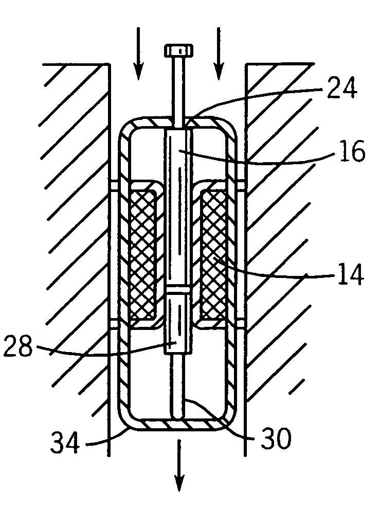
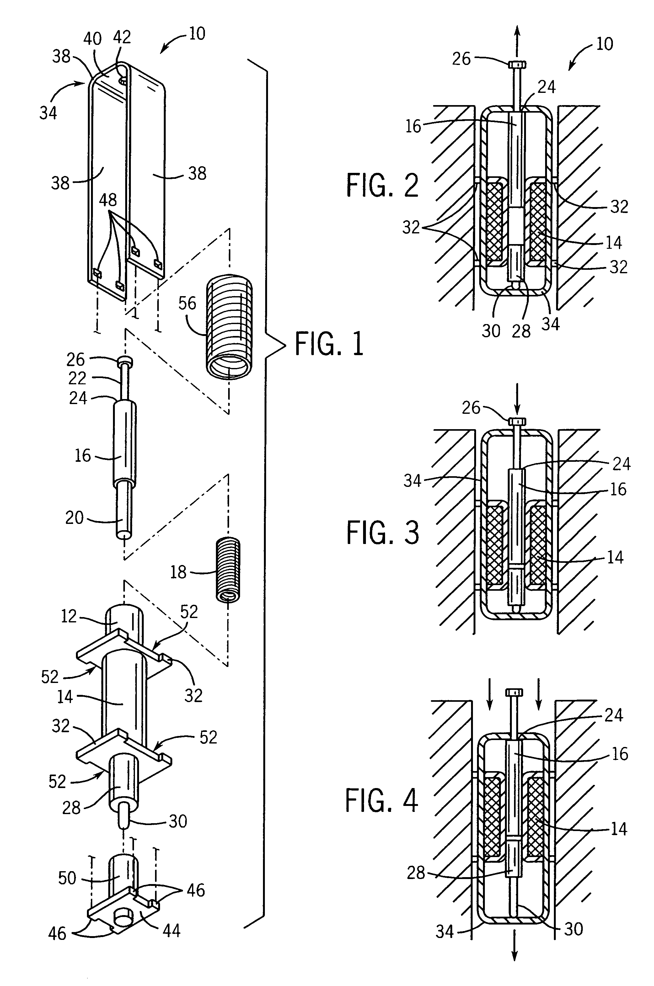
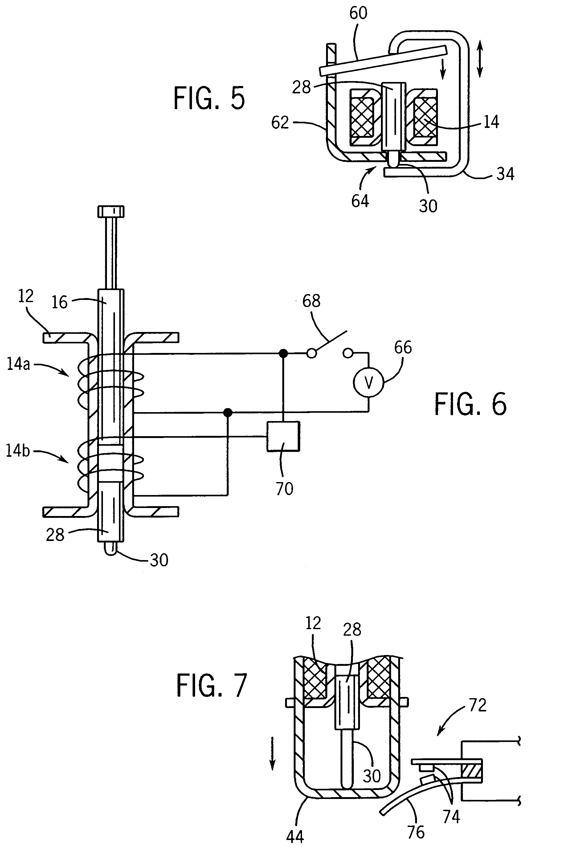
[0034]Referring to FIG. 1, an actuator 10 of the present invention provides generally a tubular form 12 about which a solenoid coil 14 may be wound. The tubular form 12 includes a central bore (not visible in FIG. 1) which may receive a generally cylindrical ferromagnetic plunger 16 typically constructed of iron or steel. The plunger 16 may slide smoothly within the bore of the tubular form 12 as attracted by the solenoid coil 14 when the latter is energized.

[0035]The solenoid coil 14, as is understood in the art, is a coil of conductive wire and includes terminals or leads (not shown) for introducing a current into the solenoid coil to generate an axial magnetic field.

[0036]The plunger 16 includes a reduced diameter inner end 20 that may engage the inside diameter of helical return spring 18. The helical return spring 18, in turn, has an outside diameter fitting freely within the bore of the tubular form 12. In its relaxed state, the helical return spring 18 extends beyond the inne...


PUM


Abstract

A fast engage, slow release electrical actuator combines an electromagnetic actuator with a thermal actuator, the latter which retains the electromagnetic actuator after the former has been actuated to delay the release thereof.

Description

CROSS-REFERENCE TO RELATED APPLICATIONS[0001]This claims the benefit of Provisional Application No. 60 / 524,232, filed on Nov. 21, 2003.BACKGROUND OF THE INVENTION[0002]The present invention relates to electrical actuators useful in washing machines and the like, and in particular to an actuator that provides for rapid initial engagement with delayed release.[0003]Electrical actuators that rapidly engage upon receipt of an actuation signal, but that delay releasing when the actuation signal ceases may be used, for example, in a lid lock on a clothes washing machine. With such an actuator, the lid locks quickly upon the start of the spin cycle and remains locked for a period of time after the spin cycle ends to allow the spin basket to coast to a stop before the lid can be opened. Desirably, the electrical actuator should provide a slow release not only when the actuation signal ends, but in the event of unexpected power loss.[0004]Bi-metallic actuators, known in the art, can provide ...

Claims


Application Information

Patent Timeline
Patent Type & Authority Patents(United States)
IPC IPC(8): H01H73/00H01H73/22F03G7/06
CPCF03G7/06
Inventor HINTZ, MICHAEL K.OSVATIC, MICHAEL S.HAPKE, KENYON A.
Owner ILLINOIS TOOL WORKS INC
Why Eureka
Try Eureka