Golf club

a golf club and golf technology, applied in golf clubs, golf, sport apparatus, etc., can solve the problems of prone to cracks, long carry, and not usually obtained long carry, and achieve the effect of reducing the amount of backspin, long carry, and low cos

Inactive Publication Date: 2005-09-20
ENDO MFG COMPANY +1
View PDF9 Cites 75 Cited by
  • Summary
  • Abstract
  • Description
  • Claims
  • Application Information

AI Technical Summary

Benefits of technology

[0027]As described in detail above, a golf club according to the present invention is a golf club whereby the amount of backspin can be decreased not only when the loft angle is small but also when the loft angle is large, thanks to the provision of a weight towards the back surface of the crown section, and as a result can achieve a long carry even when the trajectory is low. Also, while the external appearance is the same as conventionally, in comparison with a conventional golf club the cost aspect involves solely addition of a weight. Thus, considering the benefit obtained, low cost is achieved.

Problems solved by technology

Although the face section i.e. the striking surface is the most important factor, the loft angle is also a factor which cannot be neglected in achieving carry.
In general, if the loft angle is small, the ball flies in a condition closer to the horizontal and a long carry is not usually obtained.
On the other hand, if the loft angle is large, the ball flies upwards and in this case also a long carry is not obtained.
In order to achieve this, golf clubs are known of a construction facilitating flexing by making the crown section of another material, but they are liable to the formation of cracks.
Thus there are various problems concerning golf clubs and various studies have been made.
For example, Laid-open Japanese Patent Application No. 11-333037 proposes a golf club in which a weight is disposed at the crown section and the face section, but this does not guarantee an optimum relationship of the speed of backspin rotation and carry.
However, although, in order to obtain a large launching angle, the loft angle suitably tends to be large, as described above, this increases the amount of backspin, giving rise to the problem that the ball rises and hence does not travel far.
As described above, expedients have been adopted in order to increase the carry under various conditions, but the problems have not necessarily been satisfactorily solved.

Method used


Image

  • Golf club
  • Golf club
  • Golf club

Examples


Embodiment Construction

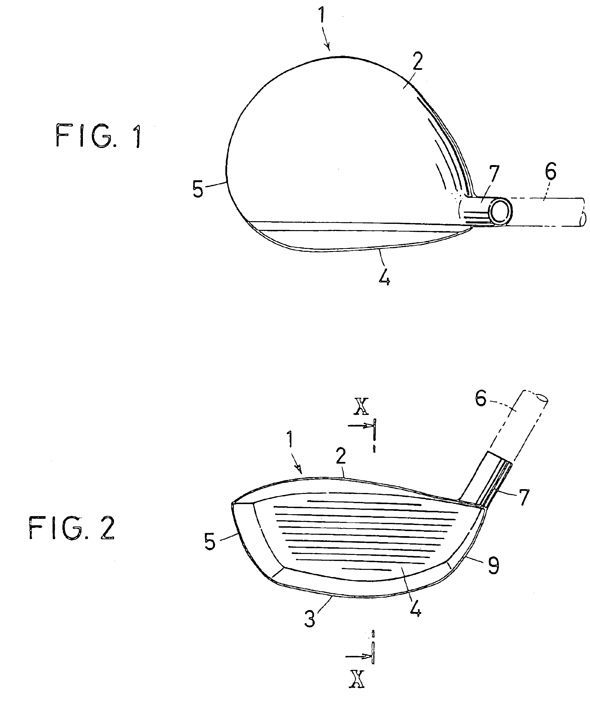
[0047]FIG. 1 and FIG. 2 are external views of a golf club according to the present invention, FIG. 1 being a plan view and FIG. 2 being a front view. The subject of the golf club of the present invention is a hollow metal golf club head. In the actual condition of use, the golf club head is arranged to be supported on a shaft, not shown. In the embodiment, the description will be restricted solely to the head.

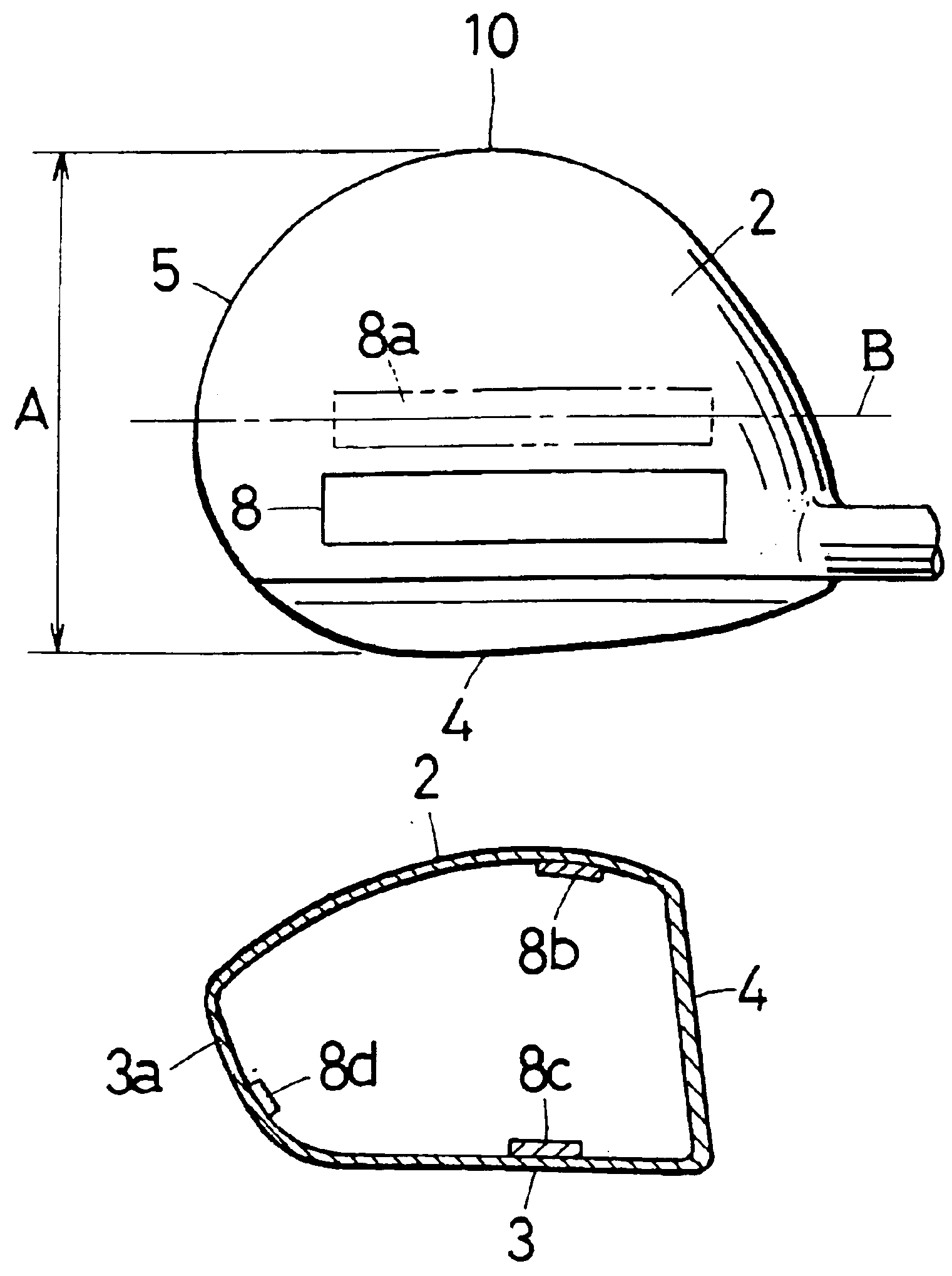
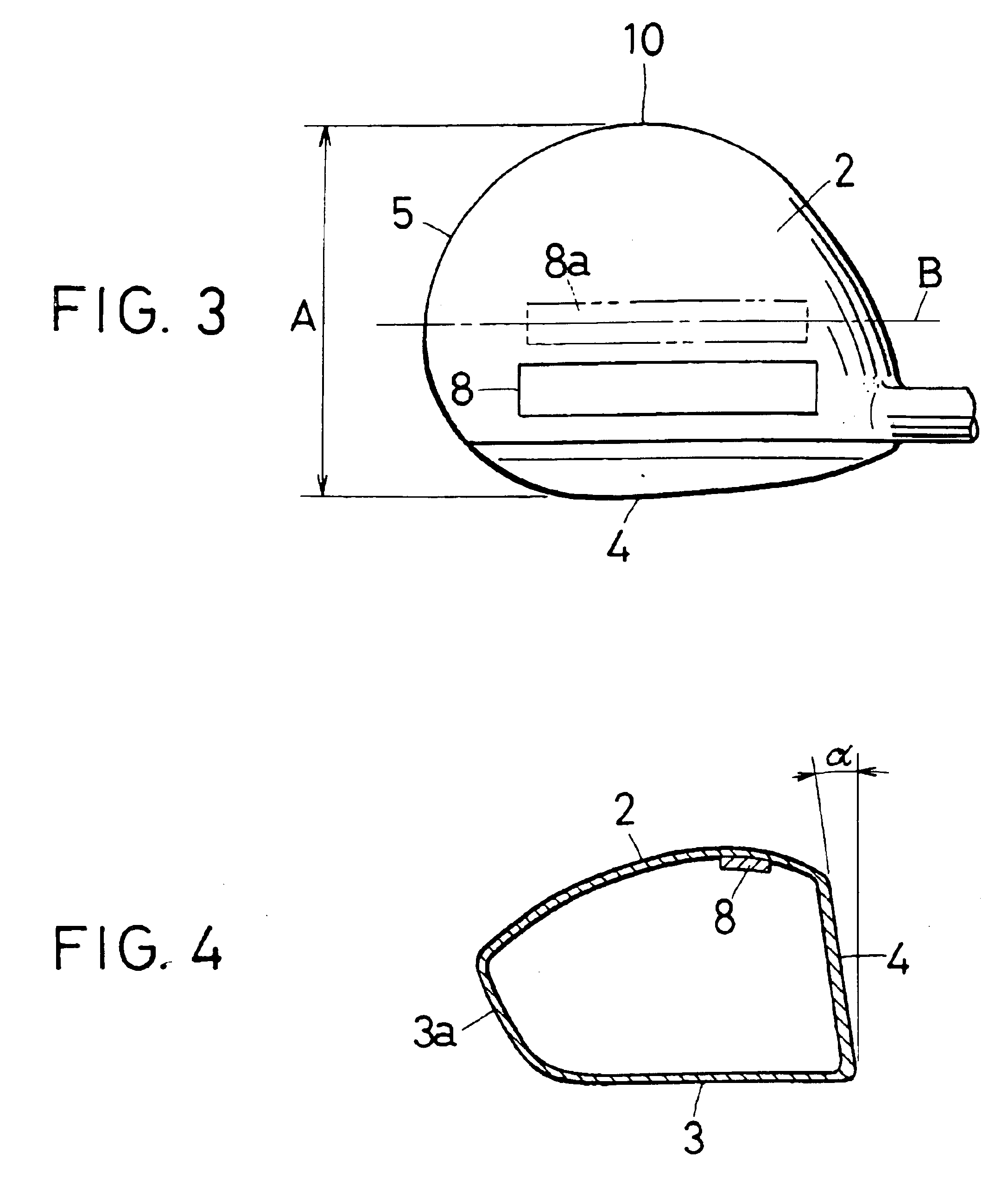
[0048]FIG. 1 to FIG. 6 show an embodiment of a driver club head 1 (hereinbelow also referred to as a head 1) in a metal golf club according to the present invention. FIG. 3 shows the construction of a weight constituting a chief feature of the present invention. The construction of the driver club head 1 will now be described. This head 1 chiefly comprises a crown section 2 corresponding to the top, a sole section 3 corresponding to the bottom, a face section 4 that hits the golf ball, a toe section 5 corresponding to the front of the head 1, a hosel 7 constituting a member for...


PUM


Abstract

A golf club is provided in which, whether the loft angle is small or large, backspin is reduced and there is no decrease in carry. A golf club construction is obtained wherein, in a driver club head (1) comprising a face section 4 having a striking surface, a sole section (3) forming the bottom, a crown section (2) forming the top and a back section (3a) forming the back portion, when the loft angle is small, the amount of backspin is reduced and performance is maintained, and even when the loft angle is large, the amount of backspin is reduced and a good carry distance is achieved. For this purpose, the crown section (2) is improved, with the provision of a weight (8) on the inside surface thereof nearer to the face section than the center of the surface

Description

BACKGROUND OF THE INVENTION[0001]1. Field of the Invention[0002]The present invention relates to a golf club. In more detail, it relates to a golf club which is improved by arranging a weight, chiefly in the crown section, in order to improve carry.[0003]2. Description of the Related Art[0004]Usually, when teeing off, a golf club called a “driver” is employed in order to achieve a long carry. The carry directly influences the score, so conditions at the impact point on the head of the golf club represent a vital factor. Although the face section i.e. the striking surface is the most important factor, the loft angle is also a factor which cannot be neglected in achieving carry.[0005]In general, if the loft angle is small, the ball flies in a condition closer to the horizontal and a long carry is not usually obtained. On the other hand, if the loft angle is large, the ball flies upwards and in this case also a long carry is not obtained. As described above, the optimum loft angle is s...

Claims


Application Information

Patent Timeline
Patent Type & Authority Patents(United States)
IPC IPC(8): A63B53/04
CPCA63B53/04A63B53/0466A63B2053/0408A63B2053/0491A63B60/02A63B53/0408A63B60/00
Inventor KOBAYASHI, KATSUHIROKOBE, KUNIJI
Owner ENDO MFG COMPANY
Why Eureka
Try Eureka