
Golf ball

a golf ball and ball technology, applied in the field of golf balls, can solve the problems of insufficient carry, inability to achieve sufficient carry, and inability to continue the lift of golf balls for a long time, so as to prevent the upward blowing and increase the flight duration

Inactive Publication Date: 2014-09-02
BRIDGESTONE SPORTS
View PDF14 Cites 3 Cited by
  • Summary
  • Abstract
  • Description
  • Claims
  • Application Information

AI Technical Summary

Benefits of technology

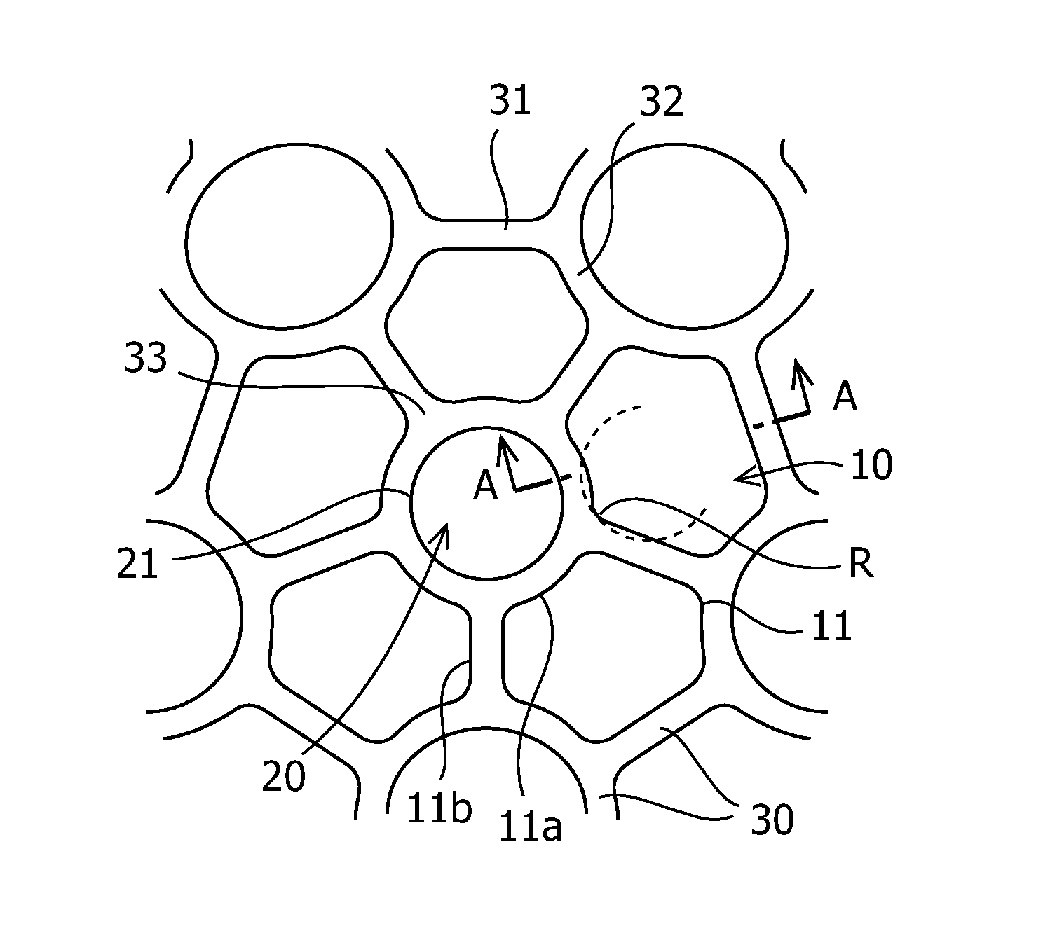
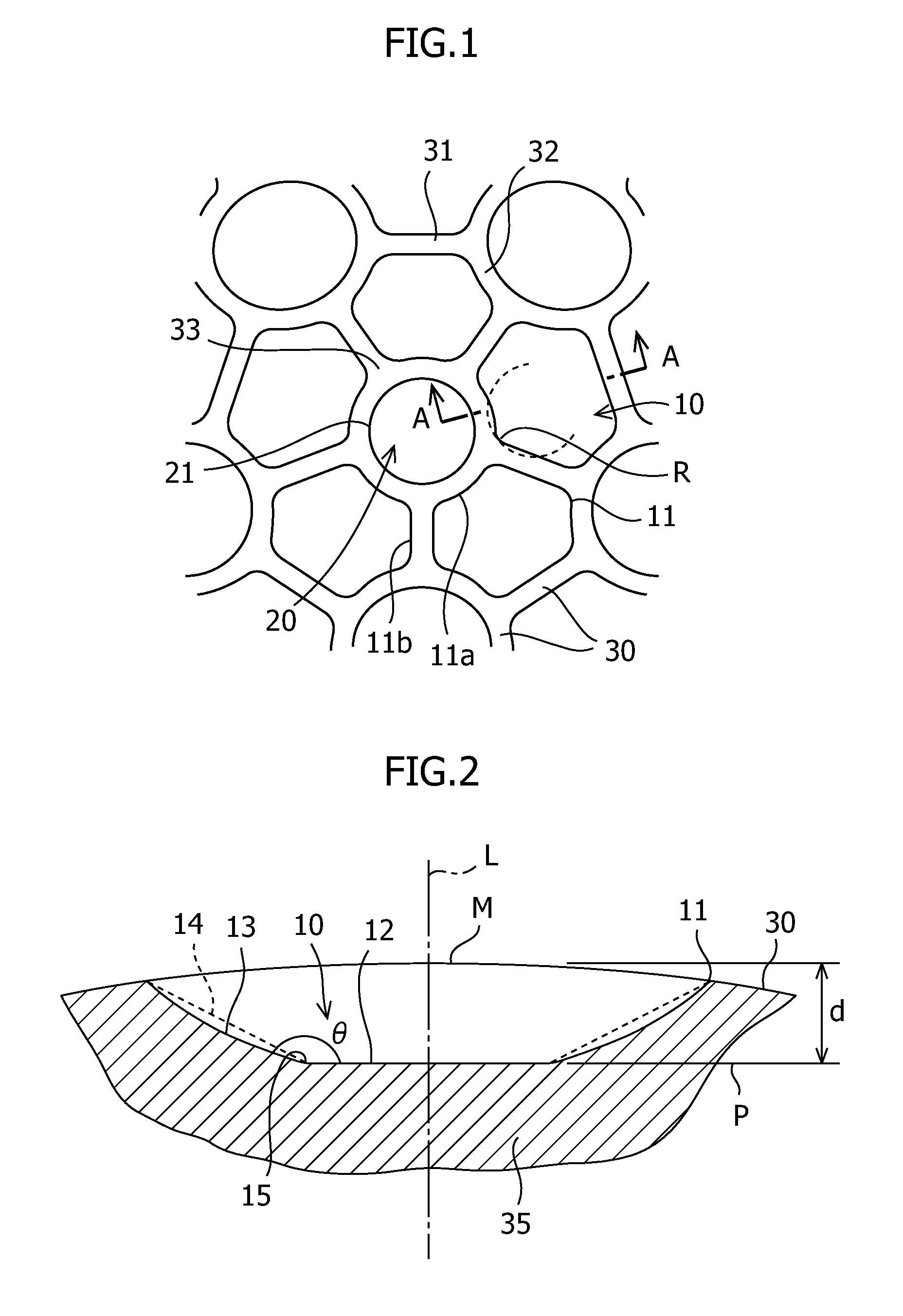
[0005]Accordingly, an object of the present invention is to provide a golf ball configured so that even if the surface occupancy ratio of dimples is increased, the depth of the dimple is kept shallow so as to restrain a lift acting on the golf ball flying in a high-speed region after the ball has been hit, and the lift of the golf ball flying in a low-speed region in the latter half of trajectory is maintained for longer, by which a longer carry can be obtained.
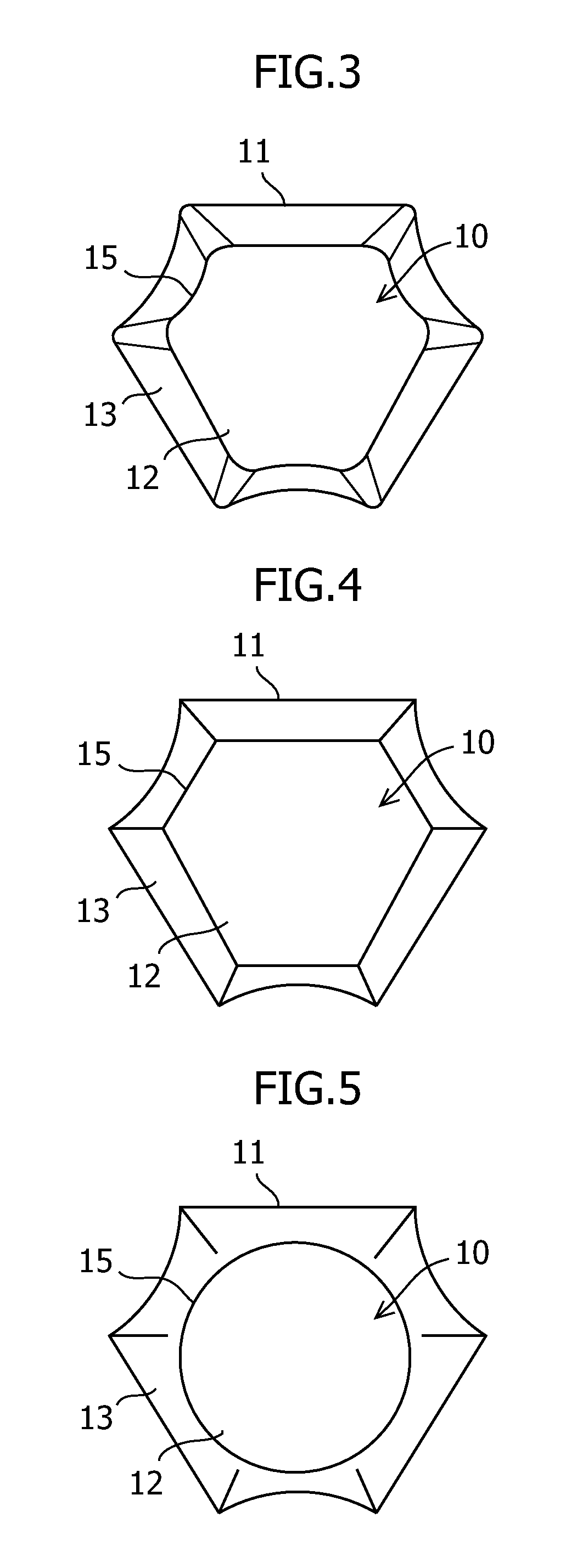
[0009]Thus, according to the present invention, at least about 10% of the dimples among the total dimples formed on the golf ball are made noncircular dimples in which a boundary line between a land part and the dimple comprises a curved line part and a straight line part, and the bottom surfaces of the noncircular dimples are made flat. The bottom surfaces of circular dimples are also made flat. Thereby, the dimples are formed so as to be shallow. Therefore, even if the surface occupancy ratio of dimples is high, a proper total volume of dimples can be maintained. Thereby, a lift that is acting on the golf ball flying in a high-speed region after the ball has been hit is restrained, and blowing upward can be prevented. Also, the lift of the golf ball flying in a low-speed region in the latter half of trajectory is maintained for longer, and the flight duration can be increased, by which the carry can be improved.

Problems solved by technology

However, the lift of the golf ball is excessive in a high-speed region after the ball has been hit, so that there is a tendency for the golf ball to be blown upward, and there is also a tendency for the lift of golf ball to not continue for long in a low-speed region in the latter half of the trajectory.
Therefore, a sufficient carry cannot be obtained.

Method used


Image

  • Golf ball
  • Golf ball
  • Golf ball

Examples


example

[0048]As example 1, a golf ball shown in the photograph of FIG. 6 was manufactured. First, the calculation of the area ratio of a typical noncircular dimple of this golf ball is explained. In this typical noncircular dimple, the bottom surface border line and the outermost border line were similar. The length of the outermost border line was 15.61 mm, and the length of the bottom surface border line was 12.19 mm. In this case, since the area S1 surrounded by the outermost border line is 19.39 mm2, and the area S2 surrounded by the bottom surface border line is 11.82 mm2, the area ratio (S2 / S1) is 61.0%. These typical noncircular dimples and noncircular dimples that were similar to the typical ones were formed in the number of 216, and circular dimples were formed in the number of 110. The surface occupancy ratio of dimples was set at 90%, the volume occupancy ratio of dimples at 1.68%, and the total volume of dimples at 683.2 mm3. The carry at the time when the golf ball of example ...


PUM


Abstract

A golf ball includes a plurality of circular dimples formed on the surface thereof, each of the circular dimples having a flat bottom surface; and a plurality of noncircular dimples formed on the surface of the golf ball, at least about 10 percent of dimples of all the dimples on the surface being the noncircular dimples, wherein a boundary line between a land part of the golf ball and the noncircular dimples each comprise a curved line part and a straight line part. The plurality of noncircular dimples each having a flat bottom surface. The bottom surface of the noncircular dimple may has a planar shape approximately similar to the boundary line. The lift coefficient CL at Re 70000 / 2000 rpm may be at least about 70 percent of the lift coefficient CL at Re 80000 / 2000 rpm, and the drag coefficient CD at Re 180000 / 2520 rpm is up to about 0.225.

Description

BACKGROUND OF THE INVENTION[0001]The present invention relates to a golf ball and, more particularly, relates to a golf ball having dimples formed on the surface thereof to improve the carry.[0002]In designing a golf ball, it is well known that to obtain a long carry when the golf ball is hit, a high coefficient of restitution inherent in the golf ball itself and low air resistance in the flight time caused by dimples arranged on the surface of golf ball are important. Usually, many dimples are arranged on the surface of a golf ball. To reduce the air resistance, there have been proposed various methods for arranging the dimples on the surface of golf ball at a density that is as high as possible and uniformly.[0003]Japanese Patent Application Publication No. 2006-095281 and Japanese Patent Application Publication No. 2008-12299 describe that by arranging noncircular dimples between circular dimples, the surface occupancy ratio of dimples is increased to improve the aerodynamic perf...

Claims


Application Information

Patent Timeline
Patent Type & Authority Patents(United States)
IPC IPC(8): A63B37/12A63B37/00
CPCA63B37/0004A63B37/0012A63B37/0007A63B37/0017A63B37/0019A63B37/0018A63B37/009A63B37/0089A63B37/0021A63B37/002A63B37/00215
Inventor SATO, KATSUNORI
Owner BRIDGESTONE SPORTS
Learn More