Apparatus and method for allocating channel between MSC and IWF unit in CDMA mobile communication system

a mobile communication system and channel technology, applied in data switching networks, multiplex communication, wireless communication, etc., can solve the problems of reducing the quality of service, increasing the quantity of calls, and reducing the number of calls

Inactive Publication Date: 2005-10-18
USRCOM KOREA
View PDF8 Cites 2 Cited by
  • Summary
  • Abstract
  • Description
  • Claims
  • Application Information

AI Technical Summary

Benefits of technology

[0004]It is an object of the present invention to provide an apparatus and method for allocating an E1 channel between an MSC and an IWF unit in CDMA mobile communication system, wherein an E1 super channel can be variably allocated to support both the IS-95A service for low speed calls and the IS-95B service for high speed calls.
[0005]In accordance with an aspect of the present invention, there is provided an apparatus for allocating an E1 channel between an MSC and an IWF unit in a CDMA mobile communication system, the apparatus including a channel buffer for receiving and storing call processing data; a transmission routing serial interface random access memory (“SI RAM”) for storing the E1 channel allocation information; a CPM for reading out the call processing data that are stored in the channel buffer, storing received call processing data in the channel buffer, determining whether there are more high speed calls or low speed calls in a plurality of call types currently being processed and modifying the E1 channel allocation information stored in each of the transmission routing SI RAM and the reception routing SI RAM; a multi channel controlling unit for reading out the E1 channel allocation information stored in each of the transmission routing SI RAM and the reception routing SI RAM and allocating a super channel made up of 5 channels or a super channel made up of 10 channels to the E1 channel; and a serial-parallel converting unit for converting the call processing data from the CPM to serial data and then transmitting the serial data to the IWF unit; and converting the call processing data from the IWF unit to parallel data and then transmitting the parallel data to the CPM.
[0006]In accordance with another aspect of the present invention, there is provided a method for allocating an E1 channel between an MSC and an IWF unit in a CDMA mobile communication system, the method including the steps of: by a CPM, receiving from the high-level processor call type information about a plurality of call types currently being processed; by the CPM, determining, based on the call type information, whether there are more high speed calls or low speed calls in the plurality of call types currently being processed, if there are more high speed calls in the plurality of call types currently being processed, then the CPM designates first / second super channel storage space for high speed calls of each transmission / reception routing SI RAM as an active zone and first / second super channel storage space for low speed calls of each transmission / reception routing SI RAM as a shadow zone; and by a multi channel controlling unit, reading the E1 channel allocation information that is stored in each of the first / second super channel storage space for high speed calls and allocating a super channel made up of 10 channels for high speed calls to the E1 channel; if there are more low speed calls in the plurality of call types currently being processed, then the CPM designates first / second super channel storage space for low speed calls of each transmission / reception routing SI RAM as the active zone and first / second super channel storage space for high speed calls of each transmission / reception routing SI RAM as the shadow zone; and by the multi channel controlling unit, reading the E1 channel allocation information that is stored in each of the first / second super channel storage space for low speed calls and allocating a super channel made up of 5 channels for low speed calls to the E1 channel.

Problems solved by technology

However in cases where this allocation method is applied to high speed data service based on the IS-95B standard, calls are frequently disconnected during call processing, thereby reducing the quality of service.
Calls are disconnected due to congestion caused by an increase in the quantity of data that is to be processed at the same time.

Method used


Image

  • Apparatus and method for allocating channel between MSC and IWF unit in CDMA mobile communication system
  • Apparatus and method for allocating channel between MSC and IWF unit in CDMA mobile communication system
  • Apparatus and method for allocating channel between MSC and IWF unit in CDMA mobile communication system

Examples


Embodiment Construction

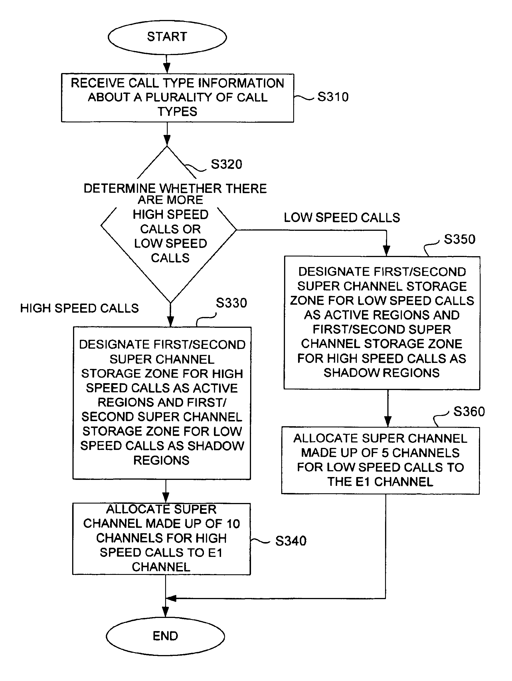
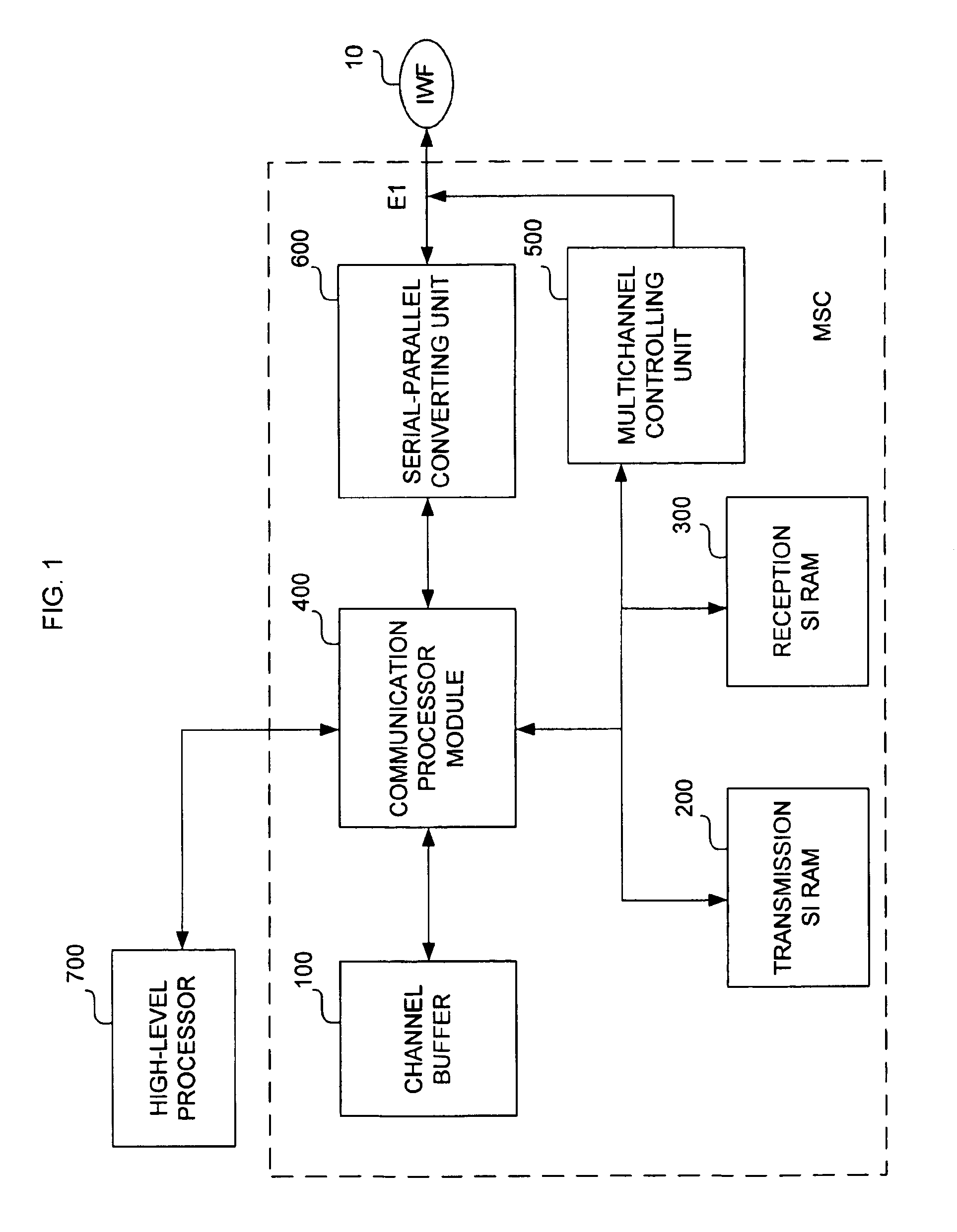
[0014]FIG. 1 is a block diagram illustrating an apparatus for allocating an E1 channel between an MSC and an IWF unit in a CDMA system in accordance with the present invention.

[0015]The apparatus for allocating the E1 channel between the MSC and the IWF unit in the CDMA system can be embodied using an “MPC8260” chip architected by MOTOROLA®.

[0016]The apparatus includes a channel buffer 100, a transmission routing serial interface random access memory (“SI RAM”) 200, a reception routing SI RAM 300, a communication processor module (“CPM”) 400, a multi channel controlling unit 500 and a serial-parallel converting unit 600.

[0017]The channel buffer 100 receives call-processing data that is transmitted from a high-level processor and stores the same therein. The channel buffer 100 also receives and stores call-processing data that is transmitted from the CPM 400.

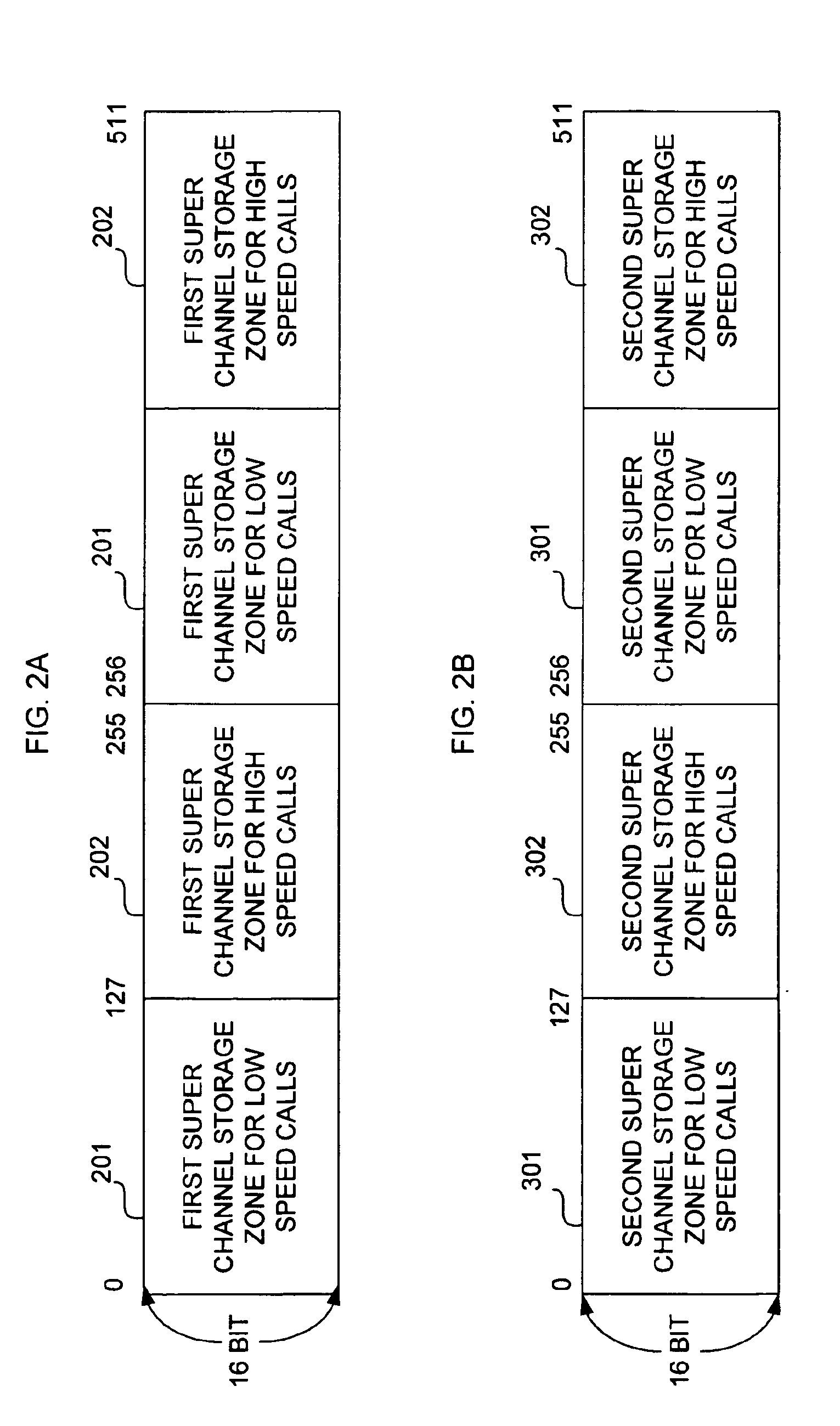
[0018]FIG. 2A shows the transmission routing SI RAM 200. The transmission routing SI RAM 200 is a routing table wherein a 16 bi...


PUM


Abstract

A device and method are provided for allocating an E1 channel between a mobile switching center (“MSC”) and an interworking function (“IWF ”) unit in a CDMA mobile communication system are provided. The method results in an E1 super channel being variably allocated to support both IS-95A service for low speed calls and IS95B service for high speed calls.

Description

FIELD OF INVENTION[0001]This invention relates to a device and method for allocating a channel in a code division multiple access (“CDMA”) mobile communication system; and more particularly, to a device and method for allocating an E1 channel between a mobile switching center (“MSC”) and an interworking function (“IWF”) unit in a CDMA mobile communication system.DESCRIPTION OF THE PRIOR ART[0002]Code division multiple access (“CDMA”) radio data service currently in service is provided based on the IS-95A standard that supports low speed (8 / 13 Kbps) data service. CDMA radio data service based on the IS-95B standard is provided at higher speed (64 Kbps), enabling more data to be processed during a predetermined period time.[0003]Currently, in order to allocate a channel between a mobile switching center (“MSC”) and an interworking function (“IWF”) unit, an E1 channel allocation method, which assumes 5 channels to be one super channel, is employed. The E1 channel allocation method is s...

Claims


Application Information

Patent Timeline
Patent Type & Authority Patents(United States)
IPC IPC(8): H04Q7/24H04B7/26H04W76/02H04J13/00H04M3/00H04W92/02
CPCH04W92/02H04B7/264H04W28/16
Inventor PARK, SANG-HOCHAI, GEUN-JIKKANG, YONG-OH
Owner USRCOM KOREA
Why Eureka
Try Eureka