Cranial bone flap fixation system and method

a cranial bone flap and fixation system technology, applied in the field of cranial surgery apparatus and method, can solve the problems of requiring a considerable amount of time and added cost, affecting the stability of the cranial bone flap, and the depression or protrusion of the flap relative to the adjacent cranium,

Active Publication Date: 2006-05-23
BIOPLATE
View PDF19 Cites 37 Cited by
  • Summary
  • Abstract
  • Description
  • Claims
  • Application Information

AI Technical Summary

Benefits of technology

[0004]It is a major object of the invention to provide improved flap fixation apparatus, system

Problems solved by technology

In some cases, fixation with wire or suture material is not secure.
Shifting of the bone flap may result in dislocation, causing depression

Method used


Image

  • Cranial bone flap fixation system and method
  • Cranial bone flap fixation system and method
  • Cranial bone flap fixation system and method

Examples


Embodiment Construction

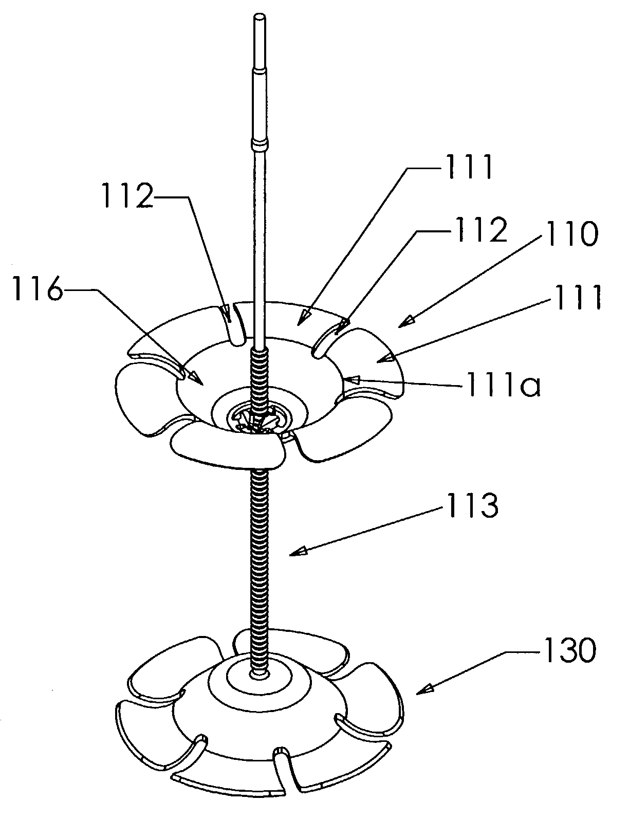
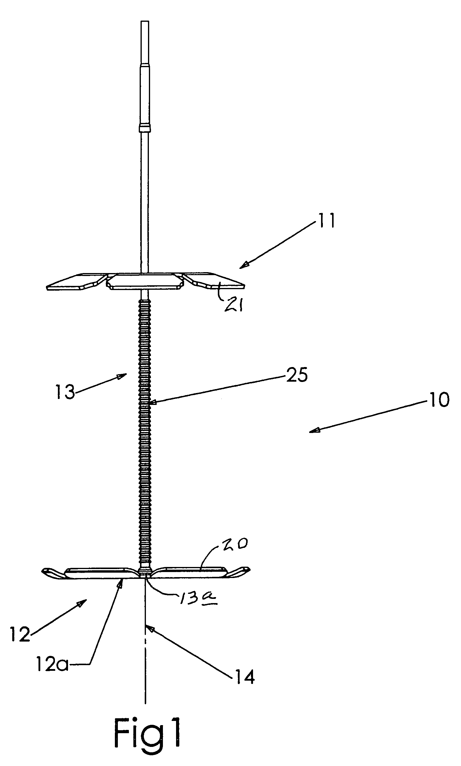
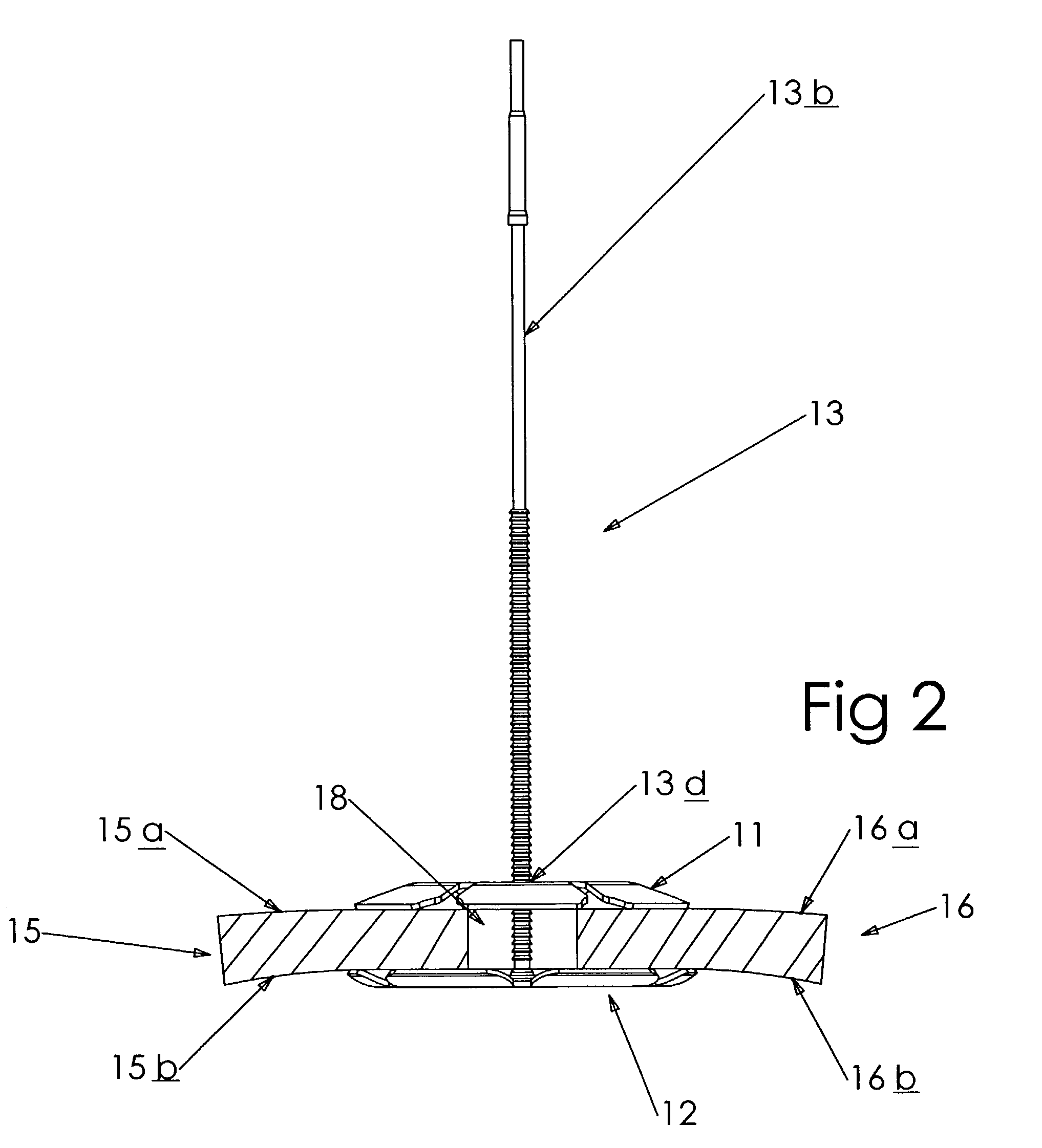
[0053]In FIG. 1 the cranial bone and bone flap fixation device 10 comprises first and second caps 11 and 12 between which portions of cranial bone and bone flap are to be gripped. A mounting post 13 is located to allow relative cap movement lengthwise of an axis 14 defined by the post. FIG. 2 shows the caps after such relative movement toward one another, to close toward and against upper and lower, or opposite surfaces 15a and 15b of cranial bone 15, and against upper and lower, or opposite, surfaces 16a and 16b of bone flap 16. Typically, the lower end 13a of post 13 is attached to or integral with the central region 12a of cap 12, and projects through kerf or gap 18 formed between 15 and 16 during surgery, and through cap 11. The caps are urged toward one another while in engagement with surfaces 15a and 15b, 16a and 16b, as by upward pulling of the post upper extent 13b and downward pushing of the cap 11. See also FIG. 28.

[0054]Petals 20 and 21 on the caps thereby become resilie...


PUM


Abstract

A cranial bone and bone flap fixation device, comprising first and second caps between which portions of the cranial bone and bone flap are to be gripped; a mounting post located to allow relative cap movement lengthwise of an axis defined by the post, at least the first cap, which is movable lengthwise of the post, forming peripheral petals that are spaced apart about an axis and radially outwardly of a central body portion of the cap, whereby the petals are individually and resiliently movable relative to the central body portion in directions generally parallel to the axis, and in response to gripping.

Description

BACKGROUND OF THE INVENTION[0001]This invention relates generally to cranial surgery apparatus and method, and more particularly to implant systems and methods for re-fixation of cranial bone flaps after craniotomy.[0002]Cranial bone flaps after craniotomy are typically fixed in position with wire, suture material or mini plates and screws. In some cases, fixation with wire or suture material is not secure. Shifting of the bone flap may result in dislocation, causing depression or protrusion of the flap relative to the adjacent cranium. This phenomenon occurs more frequently with the progressive shift to smaller craniotomies for minimally invasive surgical procedures.[0003]Fixation of the bone flap using mini plates and screws has improved the attachment of the bone flap. This technique, however, demands a considerable amount of time and added cost. There is need for an improved system for fixation of the bone flap to the cranium, providing for quick and easy application, optimal st...

Claims


Application Information

Patent Timeline
IPC IPC(8): A61B17/58A61B17/56A61B17/68A61B17/88
CPCA61B17/688A61B17/88
Inventor WELLISZ, TADEUSZ Z.ABIDIN, CIN K.GRAY, DEAN
Owner BIOPLATE
Why Eureka
Try Eureka