Return device for the pedals of a motor vehicle

Inactive Publication Date: 2006-06-06
ZF LEMFOERDER METALLWAREN AG
View PDF13 Cites 7 Cited by
  • Summary
  • Abstract
  • Description
  • Claims
  • Application Information

AI Technical Summary

Benefits of technology

[0003]The object of the present invention is therefore to improve a resetting device of the type corresponding to this class for pedals of motor vehicles such that the hyst

Problems solved by technology

The hysteresis occurring and consequently the pedal feel resulting therefrom is set in the resetting devices known from the state of the art by the predetermined springs and is consequently

Method used


Image

  • Return device for the pedals of a motor vehicle
  • Return device for the pedals of a motor vehicle
  • Return device for the pedals of a motor vehicle

Examples


Embodiment Construction

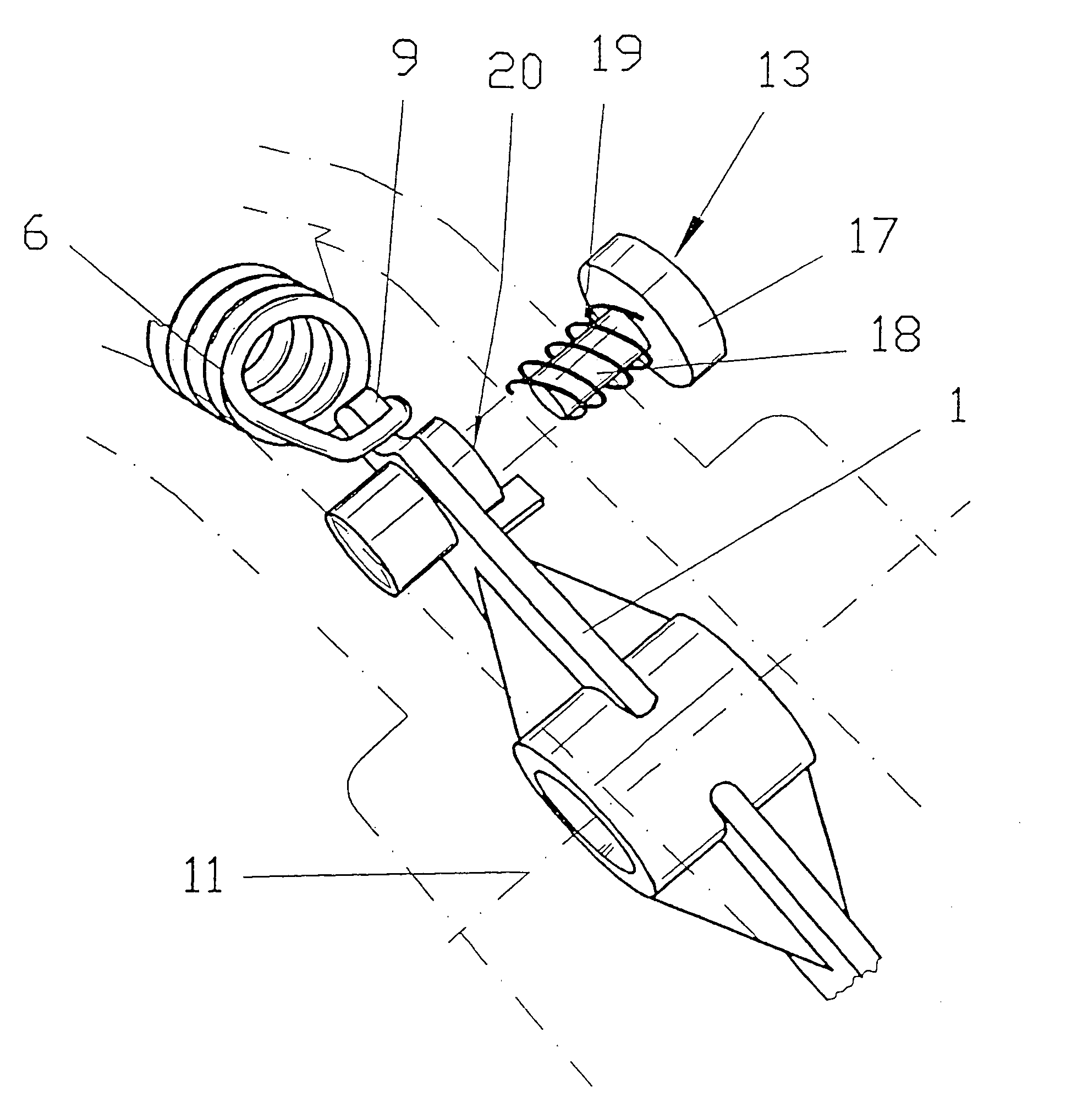
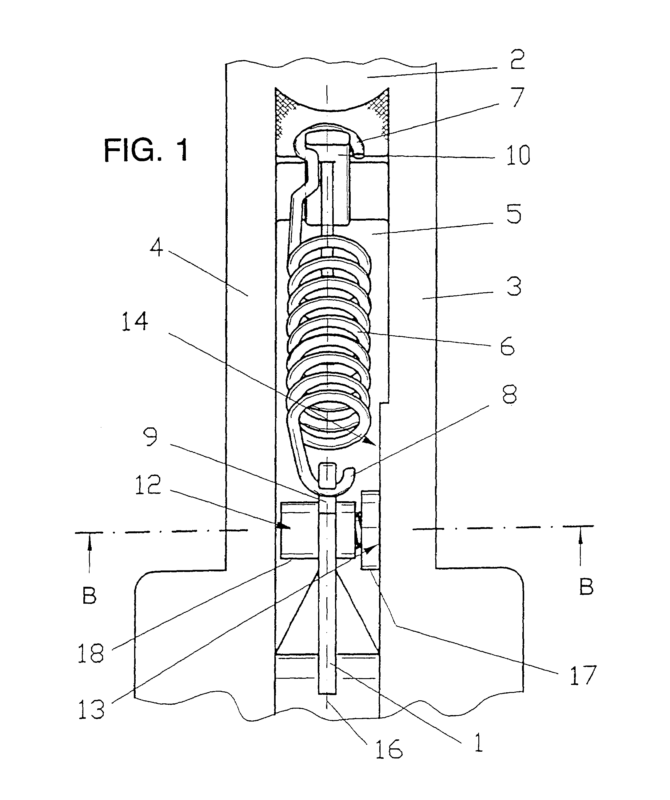
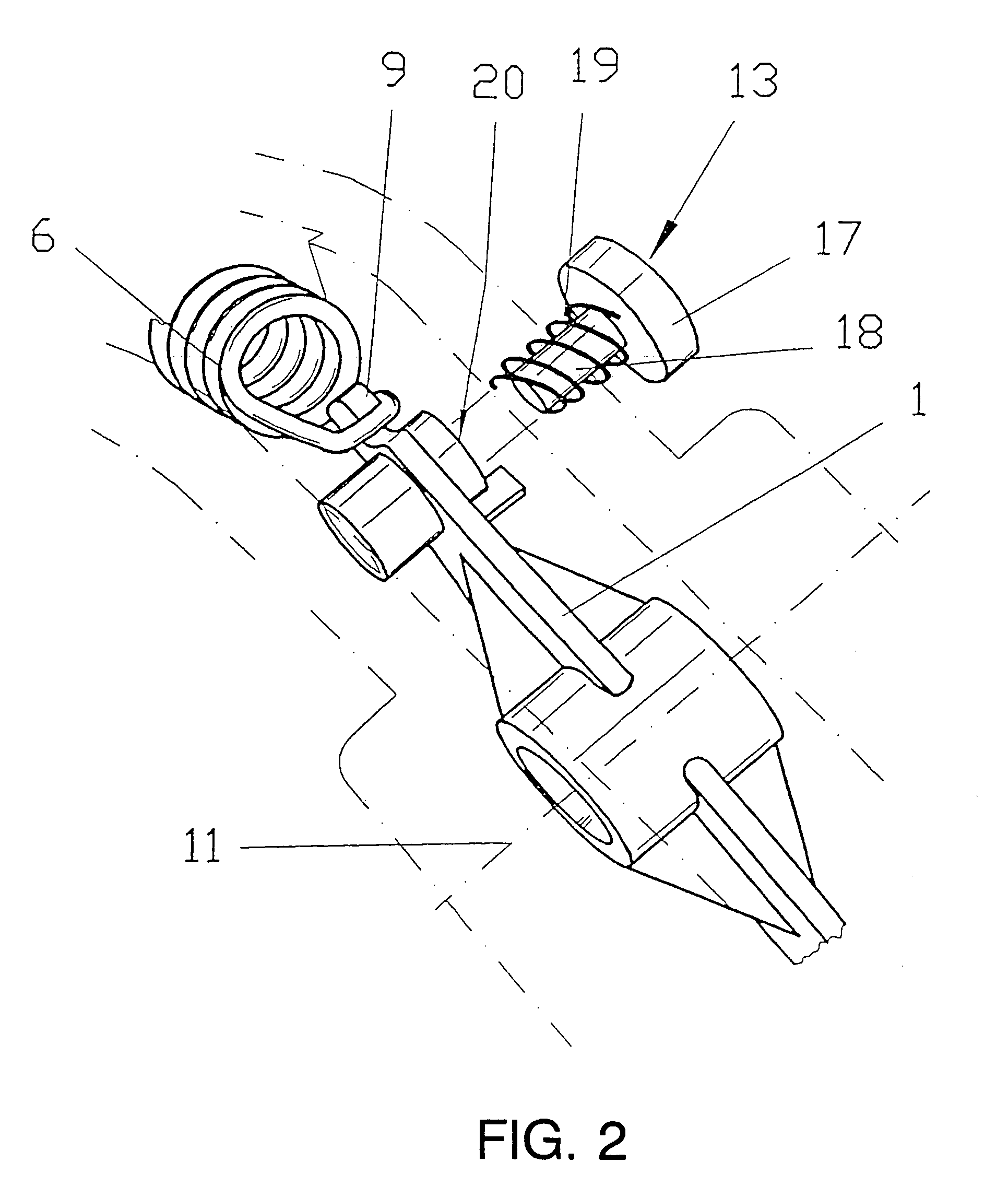
[0015]Referring to the drawings in particular, FIG. 1 shows the top part of a pedal 1, preferably for the actuation of an E gas module. The pedal 1 is mounted here in a pedal bracket 2 connected to the body of the motor vehicle. In the exemplary embodiment being shown, the pedal bracket 2 has two lateral walls 3, 4, which define between them an elongated hole 5, in which the upper part of the pedal 1 is accommodated, on the one hand. Moreover, the slot 5 also accommodates a spring element 6 designed as a tension spring for generating resetting forces for the pedal 1. The spring element 6 has hooks 7, 8 at its free ends for articulating the spring element 6 to a pedal-side mount 9, on the one hand, and to a body-side mount 10, on the other hand. During the rotation of the pedal 1 around an axis of rotation 11 located between the walls 3 and 4 (see FIG. 2), the spring element 6 is elongated and pulls the pedal 1 back into its starting position after the end of the deflecting movement ...


PUM


Abstract

A resetting device for pedals of a motor vehicle is provided with a spring element (6), which is fixed on a mount (9) at the pedal (1), on the one hand, and, on the other hand, at a corresponding mount (10). At least one spring-loaded friction element (12) is provided with at least one friction surface pair (13, 14). The friction surface pair (13, 14) is arranged between the pedal (1) and the body of the motor vehicle.

Description

FIELD OF THE INVENTION[0001]The present invention pertains to a resetting device for pedals of a motor vehicle, which pedals are mounted on an axis of rotation, with a spring element, which is fixed on a mount at the pedal, on the one hand, and, on the other hand, on a mount that is rigidly connected to the body.BACKGROUND OF THE INVENTION[0002]Various designs of pedals of a motor vehicle for actuating the brake, clutch and gas with have been known from the state of the art. The spring elements usually comprise tension springs, which are hung with one of their ends into a mounting device at the pedal and the other free end is articulated to a hook or the like on the body. Besides tension springs, resetting devices equipped with compression springs have also been known, especially in the case of resetting devices for electronic module units for scanning the position of the gas pedal and transmitting the data thus obtained to downstream assembly units (E gas modules). Due to the sprin...

Claims


Application Information

Patent Timeline
IPC IPC(8): G05G1/30B60T7/06B60K23/02G05G5/03
CPCG05G1/30G05G5/03Y10T74/2054Y10T74/20534Y10T74/20528Y10T74/20888
Inventor BURGSTALER, ANDREEDUTZ, JANPATZOLD, SIMONE
Owner ZF LEMFOERDER METALLWAREN AG
Why Eureka
Try Eureka