Light emitting diode device

a technology of light-emitting diodes and diodes, which is applied in the direction of static indicating devices, instruments, luminescent compositions, etc., can solve the problem that the red light is scarcely included in the passing range of the red light filter

Active Publication Date: 2006-06-13
CITIZEN ELECTRONICS CO LTD
View PDF3 Cites 108 Cited by
  • Summary
  • Abstract
  • Description
  • Claims
  • Application Information

AI Technical Summary

Benefits of technology

[0009]According to the present invention, there is provided an LED device comprising a white LED device having a substrate a blue LED mounted on the substrate for emitting blue light, a transparent resin covering the blue LM and including phosphor particles each of which has a quality to convert blue light to white l

Problems solved by technology

However, when red is selected, red light is scarcely

Method used


Image

  • Light emitting diode device
  • Light emitting diode device
  • Light emitting diode device

Examples


Embodiment Construction

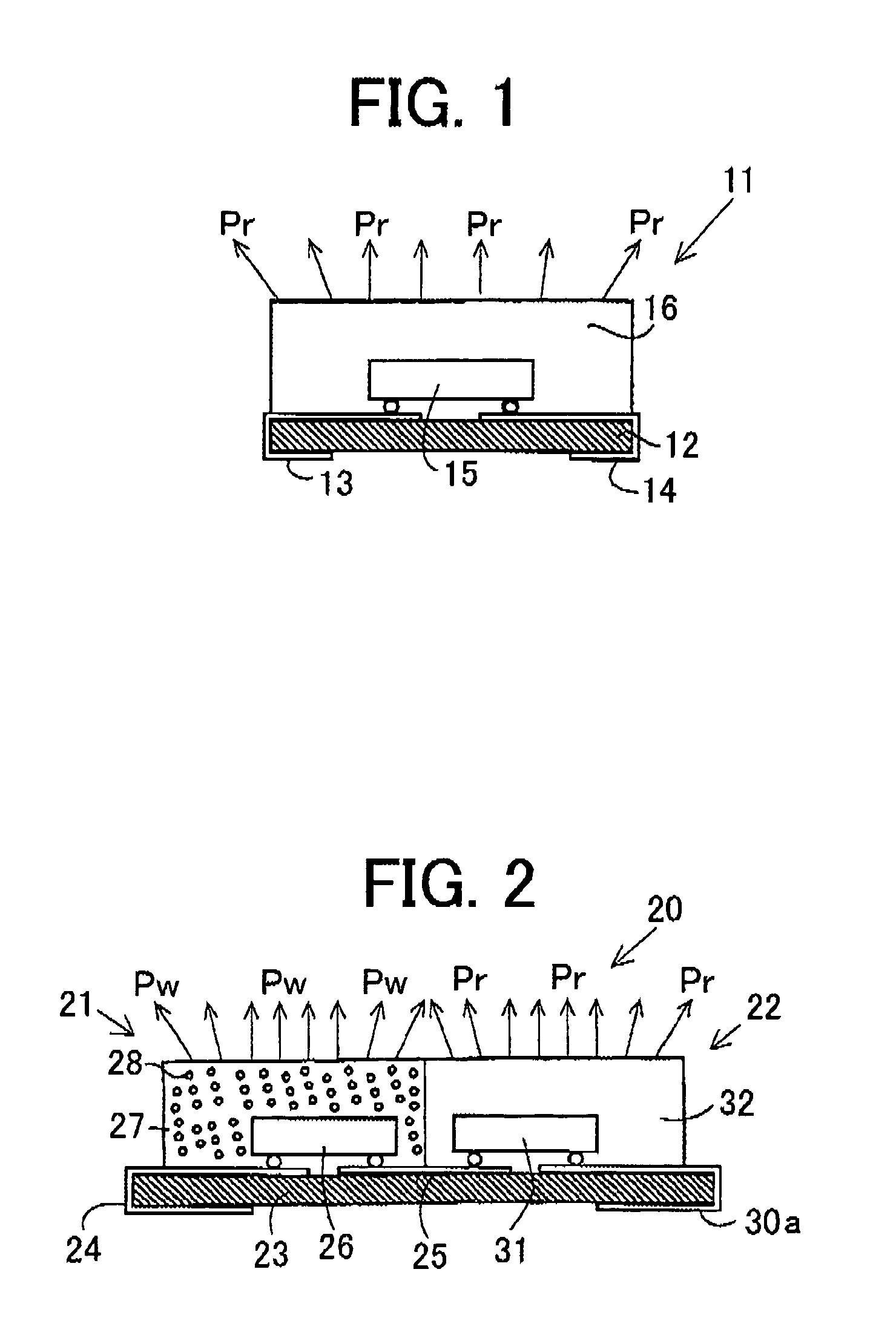
[0023]FIG. 1 is a sectional view showing a red LED device used in an LED device of the present invention.

[0024]The LED device 11 comprises a substrate 12 having a pair of terminal electrodes 13, 14 provided on the upper surface and the underside thereof, and a red LED 15 emitting red light. The LED 15 and the upper surface of the substrate 12 are covered by a transparent resin 16.

[0025]When a driving voltage is applied to the terminal electrodes 13 and 14, the LED 15 is excited to emit red light Pr.

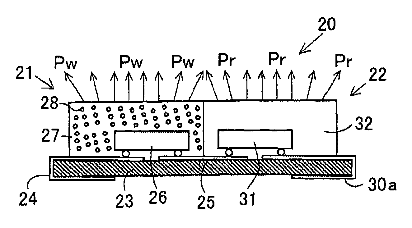
[0026]Referring to FIG. 2 showing a sectional view of an LED device 20 according to a first embodiment of the present invention, the LED device 20 comprises a white LED device 21 emitting bluish white light and a red LED device 22 emitting red light, both the devices being provided on a common substrate 23.

[0027]The white LED device 21 comprises the substrate 23 having a pair of terminal electrodes 24, 25 provided on the upper surface and the underside thereof, and a blue LED 26 emitting ...


PUM


Abstract

An LED device comprises a white LED device and a red LED device. The white LED device has a substrate, a blue LED mounted on the substrate for emitting blue light, a transparent resin covering the blue LED and including phosphor particles. The phosphor particle has a quality to convert blue light to white light, if the particle contacts with the blue light. The red LED device has a substrate, a red LED mounted on the substrate for emitting red light, and a transparent resin covering the red LED device is disposed so that emitted red light mixes with the white light emitted from the white LED device.

Description

BACKGROUND OF THE INVENTION[0001]The present invention relates to a light emitting diode device using a light emitting diode (LED), for illuminating a display such as a liquid crystal display.[0002]FIG. 8 is a sectional view showing a conventional LED device of a fluorescence color mixing type for emitting white color light.[0003]The LED device 10 comprises a substrate 1 having a pair of terminal electrodes 2, 3 provided on the upper surface and the underside thereof, and a blue LED 4 emitting blue light. The LED 4 and the upper surface of the substrate 1 are covered by a transparent resin 5. In the resin 5, phosphor particles 6 of YAG are mixed. The LED device 10 emits white light Pw by color mixing as described hereinafter.[0004]Referring to FIG. 9 which is an enlarged view of a part of FIG. 8, when a driving voltage is applied to the terminal electrodes 2 and 3, the LED 4 is excited to emit blue light Pb. When the blue light Pb meets the particle 6, the blue light Pb changes into...

Claims


Application Information

Patent Timeline
IPC IPC(8): G09G3/32G09G3/14C09K11/08C09K11/64G02F1/13357G09G3/36H01L25/075H01L33/02H01L33/50H01L33/56H01L33/60
CPCH01L25/0753G02F1/133603H01L33/50H01L2924/0002H01L2924/00
Inventor SASUGA, MASATOSHIHIRAYAMA, YOSHIHISATAMURA, RYOAKIYAMA, TAKASHI
Owner CITIZEN ELECTRONICS CO LTD
Why Eureka
Try Eureka