Float switch and mounting system assembly

Inactive Publication Date: 2006-06-27
RECTORSEAL LLC
View PDF11 Cites 10 Cited by
  • Summary
  • Abstract
  • Description
  • Claims
  • Application Information

AI Technical Summary

Benefits of technology

[0006]The primary object of the present invention is to provide a float switch and mounting system assembly for use with plastic condensate collection pans to shut-off condensate flow when the amount of fluid collected in the associated pan exceeds a predetermined safe threshold depth. A further object of the present invention is to provide a float switch and mounting system assembly that is adjustable in its connection to the vertically-extending wall of a fluid collection pan so that it can be used with a variety of pans having differing wall thickness dimensions and upper edge configurations whereby installers do not incur the added expense of having to carry multiple switches for differing applications. It is a further object of the present invention to provide a float switch that is sturdy in construction for responsive and reliable operation during extended periods of use. It is also an object of the present invention to provide a float switch and mounting system assembly that has cost-effective construction for widespread distribution and use. A further object of the present invention is to provide a float swit

Problems solved by technology

When air conditioning condensate and other condensates are collected, there is often a risk of overflow and/or back-up into the system producing it.
However, currently known float switches are deficient in many ways and thereby subject to malfunction, less responsive operation, more costly installation, and/or unstable installation.
First, the collection pans used for condensate collection do not always have a sturdy construction.
Therefore, when the upstanding pan wall to which a float switch is attached bends as a result of the added weight of the mounted switch, the pan wall tends to lean in over time and when it does the float switch body no longer maintains a level orientation, making it less responsive.
Also, the plastic pans used in condensate collection applications can have varying upper edge configurations and a mounting bracket that securely attaches a switch/housing to a specific style of condensate pan so as to achieve proper float switch function, may not be able to become securely attached to a pan with a different upper edge thickness or configuration.
This requires added expense for installers and repa

Method used


Image

  • Float switch and mounting system assembly
  • Float switch and mounting system assembly
  • Float switch and mounting system assembly

Examples


Embodiment Construction

[0021]While FIGS. 1–12 show the most preferred embodiment of the present invention, it is to be understood that many variations in the present invention are possible and also considered to be a part of the invention disclosed herein, even though such variations are not specifically mentioned or shown. As a result, a reader should determine the scope of the present invention by the appended claims.

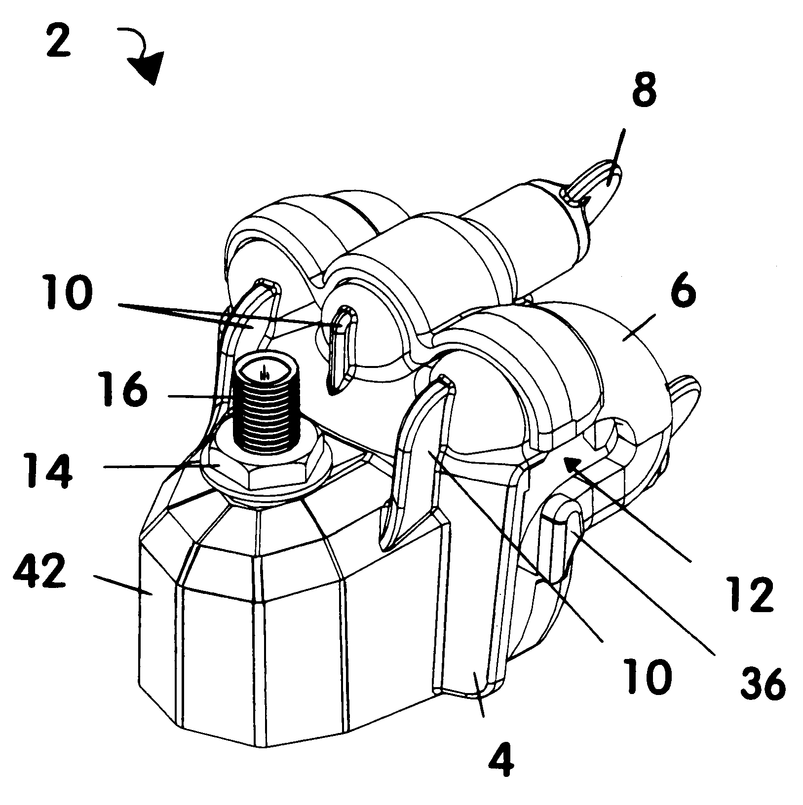
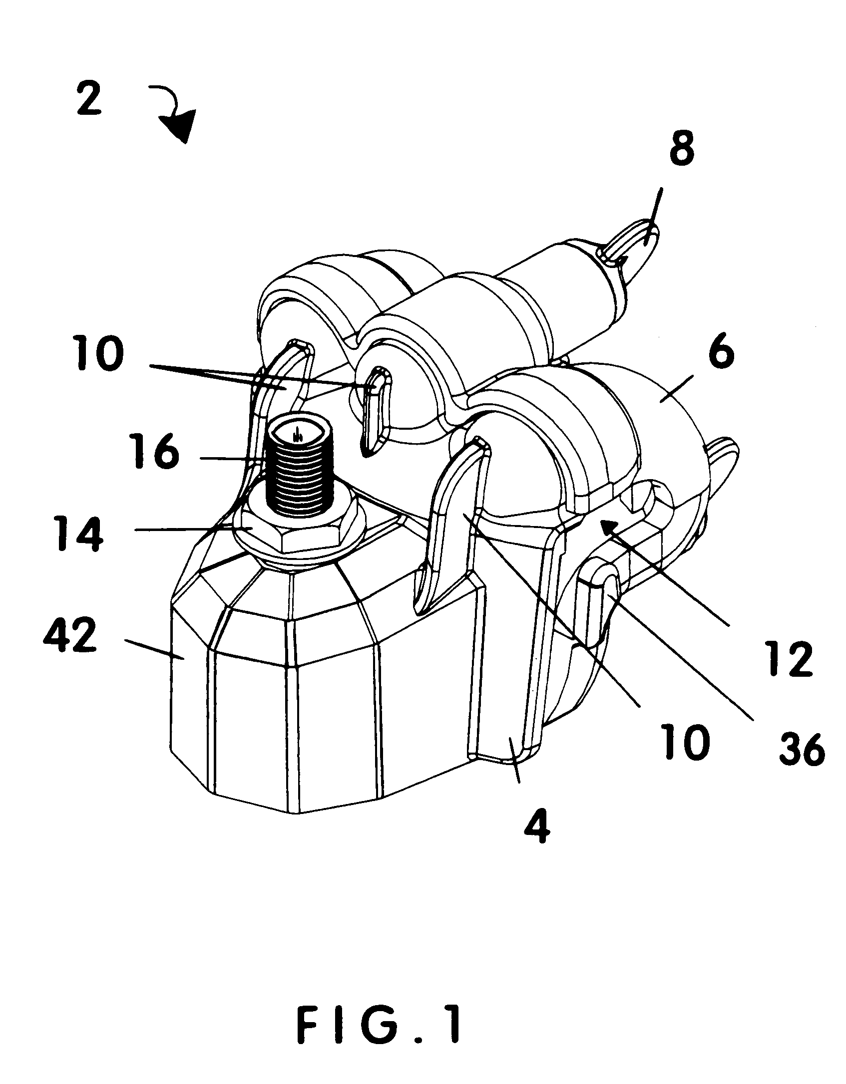
[0022]FIG. 1 shows the most preferred embodiment 2 of the present invention having a two-part housing / clamp structure adapted for attachment to a substantially vertically-extending support surface (not shown), such as but not limited to a plastic condensate collection pan used in air conditioning applications. FIG. 1 shows front part 4 and rear part 6 of most preferred embodiment 2 joined together as they would be during use. Inverted J-shaped slot 12 is where the upper edge of a condensate collection pan wall or other support surface (not shown) would be inserted and firmly secured via mul...


PUM


Abstract

A float switch assembly with a housing/clamping structure that is made from plastic and impervious to corrosion, with improvements over the prior art including a thumbscrew positioned between its two upper bracing protrusions and external braces/ribs that make it less likely for the two parts of the housing to flex relative to one another, to provide a more secure connection between the two parts of the present housing during its use to protect a float switch body within its protective housing for reliable shut-off signal activation when needed. The two housing parts are connected together over the top edge of a substantially vertically-extending support surface, such as a plastic condensate collection pan with a flange. Oversized thumbscrews facilitate and expedite installation without drilling any holes in the collection pan.

Description

CROSS-REFERENCES TO RELATED APPLICATIONS[0001]This application is a continuation-in-part of the still pending U.S. Ser. No. 11 / 124,952 now U.S. Pat. No. 6,992,260 filed by the same inventor for overlapping subject matter on May 5, 2005, which is a further continuation-in-part of U.S. Ser. No. 10 / 932,967 filed by the same inventor on Sep. 2, 2004, with improvements over the inventions disclosed in the inventor's two parent applications primarily including the addition of a thumbscrew between the two laterally positioned upper bracing members that helps to maintain the two parts of the housing / clamp structure in close association with one another when placed on the upper edge of a plastic or metal condensate collection pan in all surroundings, including those subject to wide temperature fluctuations. The additional thumbscrew allows for quick separation of the two-part housing / clamp structure prior to installation, which can take as little as ten seconds. Another improvement is the ad...

Claims


Application Information

Patent Timeline
IPC IPC(8): H01H35/18
CPCH01H35/18
Inventor CANTOLINO, CHRISTOPHER RALPH
Owner RECTORSEAL LLC
Why Eureka
Try Eureka