Polyaxial bone screw

a polyaxial bone screw and screw technology, applied in the field of polyaxial bone screws, can solve the problems of difficult alignment and seating of rods into the polyaxial screw, and the difficulty of mounting rods into the rod-receiver element of various fixation devices

Active Publication Date: 2006-08-08
HAND INNOVATIONS +1
View PDF20 Cites 512 Cited by
  • Summary
  • Abstract
  • Description
  • Claims
  • Application Information

AI Technical Summary

Benefits of technology

[0007]In another embodiment, the engagement member can be a compression cap that is disposed within the receiver member and that has a concave distal surface adapted to seat at least a portion of the spherical head of the shank. The compression cap is preferably capable of mating with the receiver member such that the compression cap is effective to retain the spherical head of the shank in a spherical recess formed in the receiver member. The compression cap can have a variety of configurations, and in one embodiment it can include opposed leaf-spring members that are adapted to contract inward, biasing the cap distally, to frictionally engage the spherical head of the shank. In another embodiment, at least a portion of the compression cap has a diameter that is expandable to frictionally engage the spherical head. By way of non-limiting example, the compression cap can include a plurality of distally-extending finger-like members formed around a distal edge of the compression cap to frictionally engage the spherical hea...

Problems solved by technology

While current spinal fixation systems have proven effective, it can be difficult to mount rods into the rod-receiving element of various fixation devices.
In particular...

Method used


Image

  • Polyaxial bone screw
  • Polyaxial bone screw
  • Polyaxial bone screw

Examples


Embodiment Construction

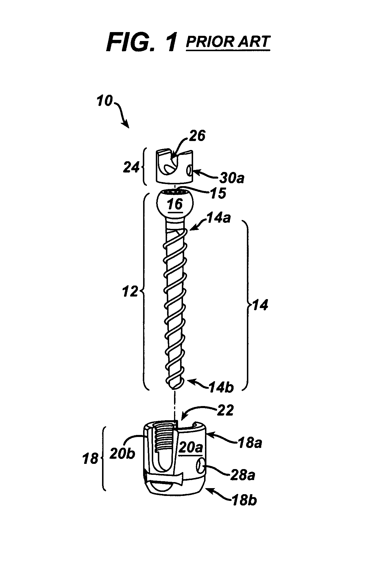
[0021]FIG. 1 illustrates a prior art polyaxial bone screw assembly 10 that includes a bone screw 12, a receiver member 18, and a compression cap 24. As shown, the bone screw 12 generally includes a threaded shank 14 having a spherical head 16 formed on a proximal end 14a thereof. An Allen or other female socket 15 is formed in the head 16 for applying torque along the axis of the shank 14 to insert the shank 14 into bone. The receiver member 18 is generally U-shaped and includes opposed side walls or legs 20a, 20b that are substantially parallel to one another and that define a rod-receiving portion 22 for seating a spinal fixation rod. A distal end 18b of the receiver member 18 includes an axial opening (not shown) formed therein and having a diameter sized to permit passage of the shank 14 therethrough while maintaining the spherical head 16 therein. The receiver member 18 further includes a spherical seat (not shown) adjacent to the distal opening for polyaxially seating the sphe...


PUM


Abstract

The present invention generally provides a polyaxial fixation device having a shank with a spherical head formed on a proximal end thereof, and a receiver member having an axial passage formed therein that is adapted to polyaxially seat the spherical head of the shank. The polyaxial bone screw further includes an engagement member that is adapted to provide sufficient friction between the spherical head and the receiver member to enable the shank to be maintained in a desired angular orientation before locking the spherical head within the receiver member.

Description

FIELD OF THE INVENTION[0001]The present invention relates to polyaxial bone screws, and in particular to a polyaxial bone screw assembly in which the bone screw can be maintained in a desired angular orientation prior to locking the bone screw with respect to the rod-receiving member.BACKGROUND OF THE INVENTION[0002]Spinal fixation devices are used in orthopedic surgery to align and / or fix a desired relationship between adjacent vertebral bodies. Such devices typically include a spinal fixation element, such as a relatively rigid fixation rod, that is coupled to adjacent vertebrae by attaching the element to various anchoring devices, such as hooks, bolts, wires, or screws. The fixation rods can have a predetermined contour that has been designed according to the properties of the target implantation site, and once installed, the instrument holds the vertebrae in a desired spatial relationship, either until desired healing or spinal fusion has taken place, or for some longer period ...

Claims


Application Information

Patent Timeline
IPC IPC(8): A61B17/86A61B17/70
CPCA61B17/8605A61B17/7037A61B17/7032A61B17/70A61B17/58A61B17/74A61B17/7035
Inventor KONIECZYNSKI, DAVID D.DOHERTY, THOMAS VINCENTWHIPPLE, DALECASEY, NIALLHALL, MARK
Owner HAND INNOVATIONS
Why Eureka
Try Eureka