Flow control system for a holding pond

a technology of flow control and holding pond, which is applied in the direction of filtration separation, separation processes, instruments, etc., can solve the problems of reducing the overall size and expensive installation

Active Publication Date: 2006-10-24
THIRSTY DUCK
View PDF11 Cites 28 Cited by
  • Summary
  • Abstract
  • Description
  • Claims
  • Application Information

AI Technical Summary

Benefits of technology

[0011]In one form there is provides a flow control module having an entrance passage that is adapted to communicate with a fluid, where the fluid is in communication with a drainage pond. An orifice is provided at a position in communication with the entrance passage, where the

Problems solved by technology

Additionally, in some embodiments the items are submerged in a concrete box beneath usable soil; however, this is an expensive installation, and of course, reducing the overall size is potentially advantageous.
In other words, the prior art is

Method used


Image

  • Flow control system for a holding pond
  • Flow control system for a holding pond
  • Flow control system for a holding pond

Examples


Embodiment Construction

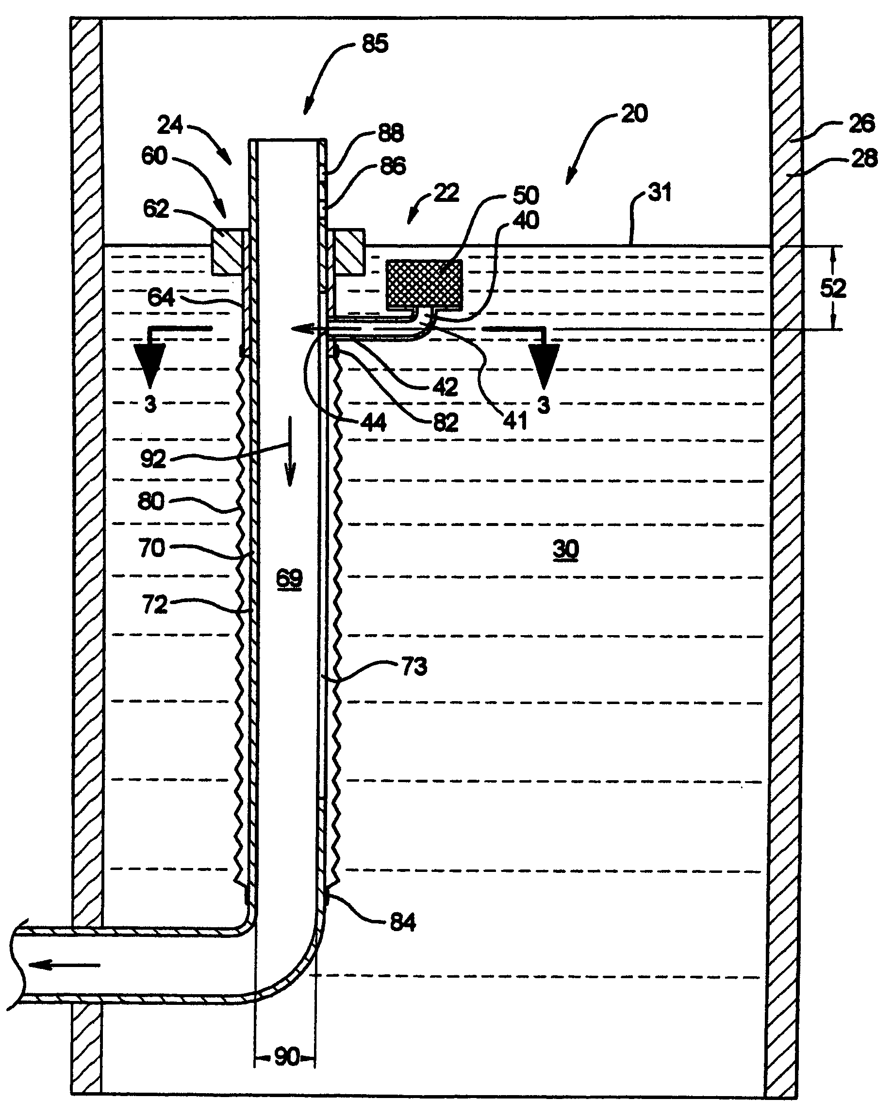
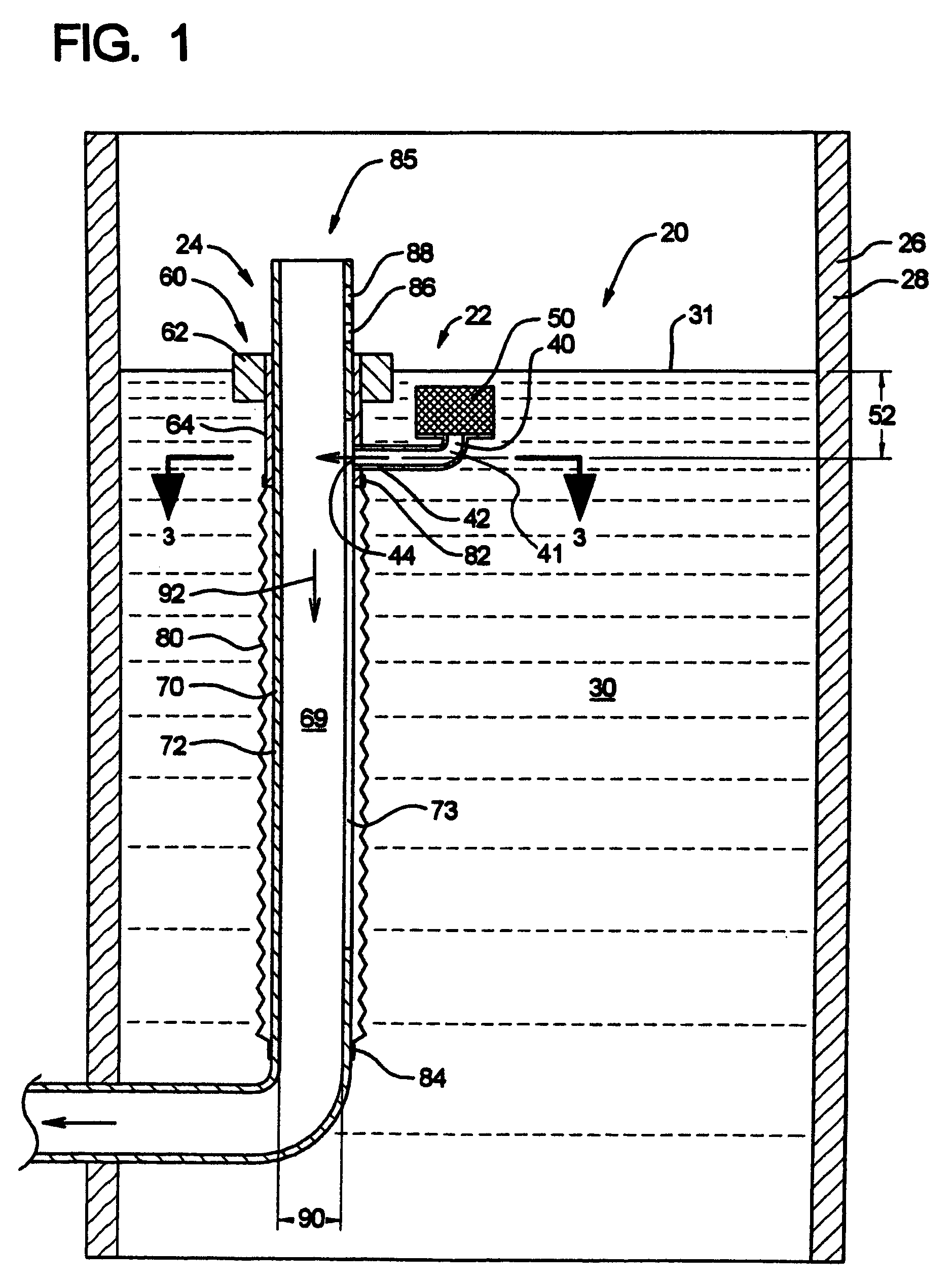
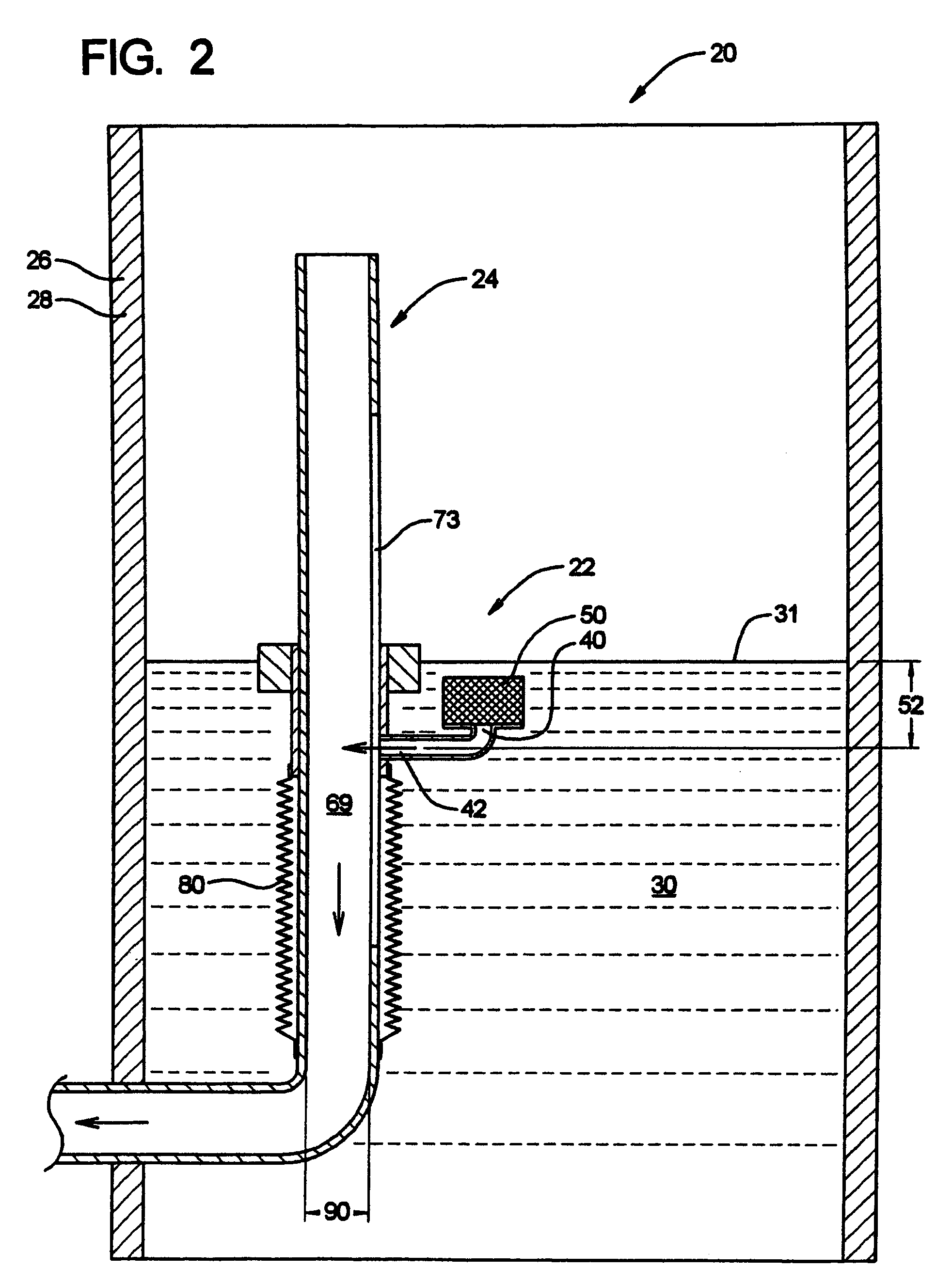
[0024]In general, the flow control assembly 20 comprises a control container 28 and a flow control system 21. The flow control system 21 comprises a flow control module 22 and a water receiving assembly 24. The general environment of the flow control system 20 is within a drainage / reservoir pond that has some form of a container 28 adjacent thereto which houses a body of water indicated at 30. The body of water 30 comprises an upper surface portion 31. Of course hydrostatic pressure results at any depth below the upper surface 31. There also is a storm drainage or the like (not shown) that is in communication with the water receiving assembly 24 that is adapted to receive the fluid therefrom. Further, there is a pond where the outlet control structure / container 20 is in communication with the pond which could be quite large up to 3 acre-feet. The volume of the control container is approximately a 48″ circle and about 8–16 feet deep which is about several hundred cubic feet. The cont...


PUM

PropertyMeasurementUnit
Fractionaaaaaaaaaa
Fractionaaaaaaaaaa
Depthaaaaaaaaaa

Abstract

An apparatus for controlling the fluid flow rate from a drainage pond that is common in developed sites where the drainage pond is adapted to supply a degree of fluid capacitance so the runoff does not overflow downstream creek beds and the like. The method and apparatus for controlling the fluid draining from a pond comprises a system for allowing a higher flow that is allowed by regulatory bodies when the pond is at a lower level so the pond drains more quickly when it is at a lower water level. Thus the apparatus allows for a smaller retention pond.

Description

RELATED APPLICATIONS[0001]This application claims priority benefit of U.S. Ser. No. 60 / 552,981, filed Mar. 12, 2004.BACKGROUND OF THE INVENTION[0002]The disclosure relates to a hydrostatic pressure flow control device particularly adapted for an above ground or below ground holding pond (generally referred to as a pond) that is adapted to collect storm water where the flow control device is in fluid communication therewith. The general purpose of the pond is to prevent a large influx of water into a nearby stream or the like which can potentially cause environmental damage. Many regulations require storm water and other runoff water to be directed into a holding pond and then discharged at an adequate flow rate to meet regulated criteria.[0003]In an urban development where forest is removed and is replaced with items such as concrete and the like which have distinctly different runoff characteristics, a detention pond must be implemented for handling storm water. In general, there a...

Claims


Application Information

Patent Timeline
IPC IPC(8): E02B3/00
CPCB01D35/027E03F5/101E03F5/107G05D7/0166
Inventor FULTON, ADAM S.
Owner THIRSTY DUCK
Why Eureka
Try Eureka