Liquid member ejecting device and method therefor, electro-optic device and manufacturing method therefor

a liquid member and ejecting device technology, applied in the direction of printing, coating, printing, etc., can solve the problems of high production cost, high production cost, waste of expensive liquid members, etc., and achieve the effect of reducing manufacturing costs

Inactive Publication Date: 2007-03-27
SEIKO EPSON CORP
View PDF6 Cites 8 Cited by
  • Summary
  • Abstract
  • Description
  • Claims
  • Application Information

AI Technical Summary

Benefits of technology

[0038]According to the above electro-optic device, a part of structural elements in the electro-optic device is formed by an ejecting device or by an ejecting method which can form various structural elements desirably; therefore, the electro-optic device is reliable and desirable. Also, it is possible to reduce a manufacturing cost because the liquid member does not lead wastefully.

Problems solved by technology

In such a case, the bubbles remaining in the ejecting head act undesirably for flowing the liquid member and ejecting the liquid member from the nozzles because the bubbles absorb ejection pressure which is generated in ejecting the liquid member.
Thus, bubbles remaining in the ejecting head is a major reason for an inferior and deteriorated ejection from the ejecting head.
However, a reagent and a test sample which are used for producing such a test sample are expensive and rare.
However, when the liquid member is filled to start using the ejection head and draining the liquid member which is filled in the ejecting head so as to remove the bubbles therein, the expensive liquid member is wasted; thus, a production cost may be greatly increased.
Also, if a rare liquid material is used, there is a disadvantage in that it is possible only to use small amount of liquid material.
Thus, production cost increases because the liquid member is wasted.
Along with a requirement for such a fine structure, it is difficult to drain the bubbles in a decompressing operation and an attracting operation due to a higher capillary attraction.

Method used


Image

  • Liquid member ejecting device and method therefor, electro-optic device and manufacturing method therefor
  • Liquid member ejecting device and method therefor, electro-optic device and manufacturing method therefor
  • Liquid member ejecting device and method therefor, electro-optic device and manufacturing method therefor

Examples


first embodiment

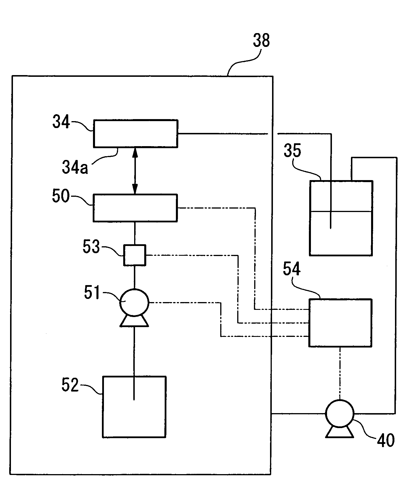
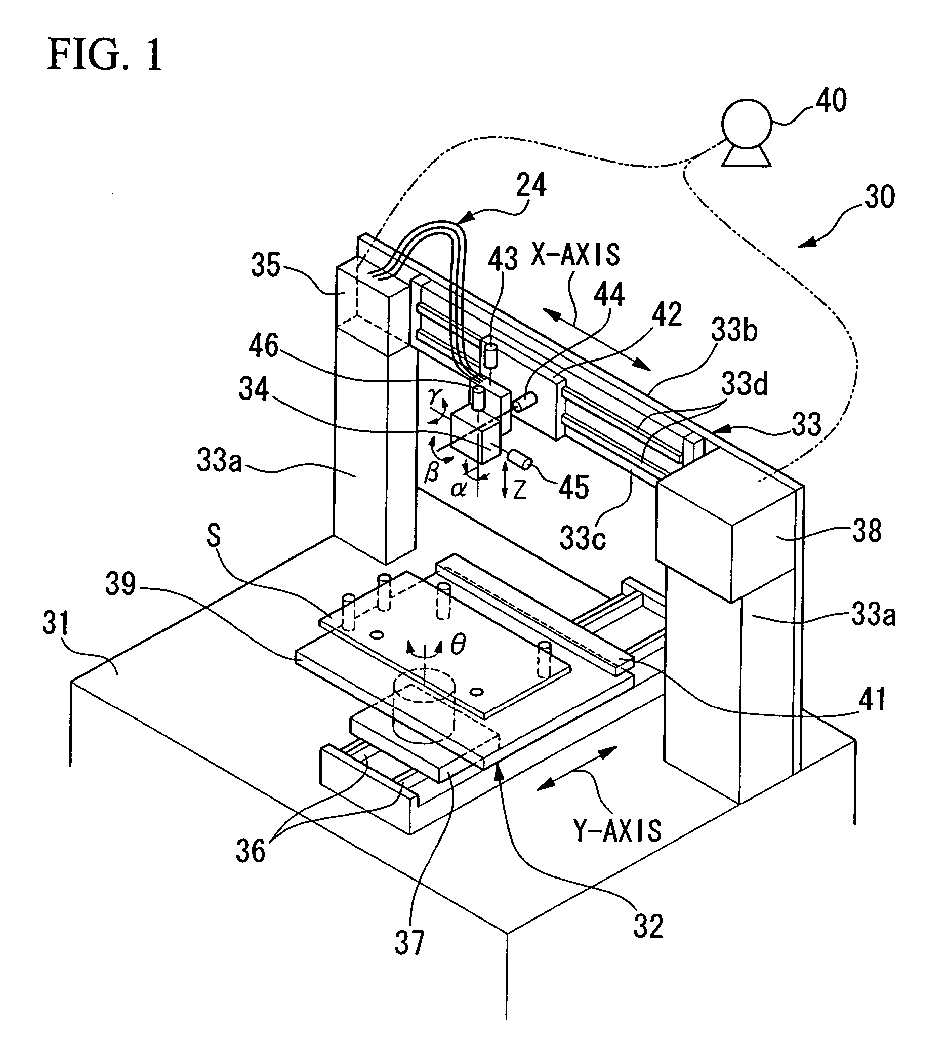
[0055]FIG. 1 shows an ejecting device for liquid member (hereinafter called an ejecting device) of the present invention. In FIG. 1, reference numeral 30 indicates an ejecting device. The ejecting device comprises a base 31, a substrate moving section 32, a head moving section 33, an ejecting head 34, a liquid member tank 35, and a chamber 38.

[0056]The base 31 is provided with the substrate moving section32 and the head moving section 33 thereon.

[0057]The substrate moving section 32 is disposed on the base 32. The substrate moving section 32 is provided with a guide rail 36 which is disposed along a Y-axis direction. The substrate moving section 32 is formed so as to move a slider 37 along the guide rail 36 by, for example, a linear motor. The slider 37 is provided with a motor (not shown in the drawing) for a θ axis. The motor is, for example a direct drive motor. A rotor (not shown in the drawing) for the motor is fixed to the table 39. When an electricity is conducted to the moto...

second embodiment

[0105]Also, in the second embodiment, it is acceptable if, for example, an attracting pad for the first attracting member and an attracting pad for the second attracting member are prepared, and / or a vacuum pump for the first decompressing section and a vacuum pump for the second decompressing section are prepared respectively; thus, a liquid member filling operation and a removing operation for bubble are performed separately by switching the above structure.

[0106]Also, in any of the above embodiments, it is acceptable if an ejecting device be formed without disposing a liquid member detecting sensor 53 therein. In such a case, a condition such as a time for filling the liquid member in side the ejecting head 34 by the first attracting member sufficiently should be found in advance by an experiment. After that, the decompressing operation and the attracting operation should be performed by the first attracting member under the above condition. Consequently, the decompressing operat...


PUM


Abstract

A liquid member ejecting device comprises an ejecting head and a liquid member tank for storing a liquid member and supplying the liquid member to the ejecting head. The liquid member ejecting device further comprises an attracting member for covering nozzles, a first decompressing section which is connected to the first attracting section for decompressing inside of the ejecting head via the first attracting member, a second attracting member for covering the nozzles, and a second decompressing section which is connected to the second attracting member so as to decompress inside of the ejecting head via the second attracting member and inside of the liquid member tank while communicating the liquid member tank. By doing this, it is possible to provide a liquid member ejecting device and method therefor, an electro-optic device, and manufacturing method therefor, and an electronic apparatus which can prevent the manufacturing cost from increasing due to the wasteful use of the liquid member so as to remove bubbles from the ejecting head while realizing a smaller nozzle diameter and finer flow paths.

Description

CROSS REFERENCE TO RELATED APPLICATIONS[0001]Priority is claimed to Japanese Patent Application No. 2003-301296, filed Aug. 26, 2003, which is hereby incorporated by reference.BACKGROUND OF THE INVENTION[0002]1. Field of the Invention[0003]The present invention relates to an ejecting device for ejecting a liquid member. More specifically, the present invention relates to a liquid member ejecting device, a method for ejecting the liquid member, an electro-optic device, and a method for manufacturing therefor, and an electronic apparatus which can fill a liquid member in an ejecting head and remove bubbles in the filled liquid member desirably.[0004]2. Description of Related Art[0005]Conventionally, an ink jet printer which is provided with an ink jet head has been known as an ejecting device which is provided with an ejecting head for ejecting the liquid member material.[0006]An ink jet head which is provided in the ink jet printer usually comprises a cavity for storing the liquid me...

Claims


Application Information

Patent Timeline
Patent Type & Authority Patents(United States)
IPC IPC(8): B41J2/165B41J2/175B41J2/19B41J2/18B05C5/00B05C11/10B05D3/00B05D7/00B41J2/01B41J2/185H01L21/48H01L27/32H01L51/50H05B33/10
CPCB41J2/16517B41J2/19H01L27/3297H01L21/4846B41J2/18B41J25/003B41J25/3086B41J25/316B41J29/02
Inventor USUI, TAKAHIRO
Owner SEIKO EPSON CORP
Why Eureka
Try Eureka