Light guide plate, lighting apparatus and liquid crystal display provided with the same, and light guide plate molding die
a technology of light guide plate and liquid crystal display, which is applied in the direction of lighting and heating apparatus, mechanical equipment, instruments, etc., can solve the problem of creating non-uniformity in illumination at the boundary portion
- Summary
- Abstract
- Description
- Claims
- Application Information
AI Technical Summary
Benefits of technology
Problems solved by technology
Method used
Image

Examples
first preferred embodiment
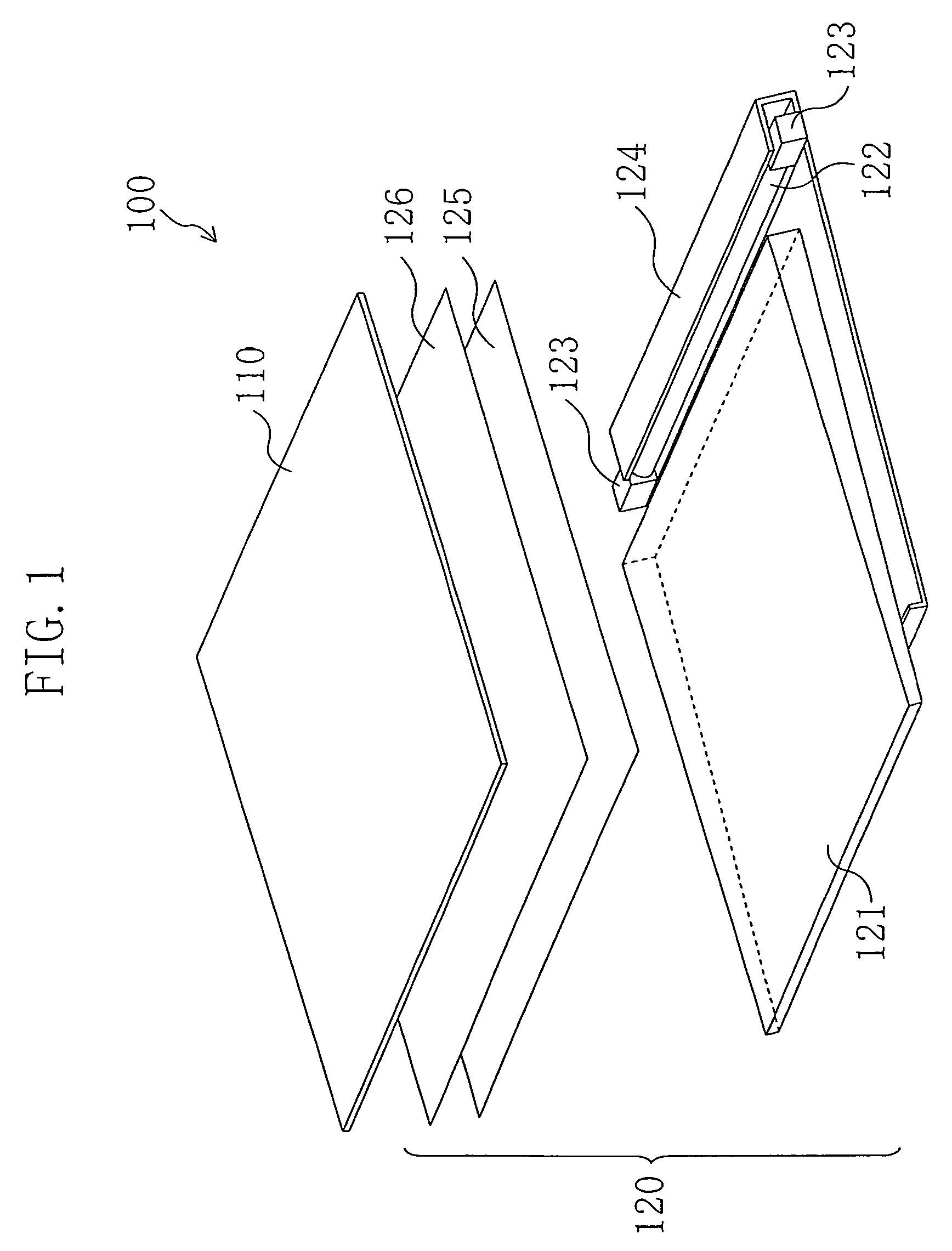
[0042]FIG. 1 is a view showing a liquid crystal display 100 according to the first preferred embodiment of the present invention.
[0043]The liquid crystal display 100 includes a liquid crystal display panel 110 and a backlight (lighting apparatus) 120 provided on the back liquid crystal display panel 110.
[0044]The liquid crystal display panel 110, which includes a liquid crystal layer sandwiched by a pair of substrates, functions as a light valve.
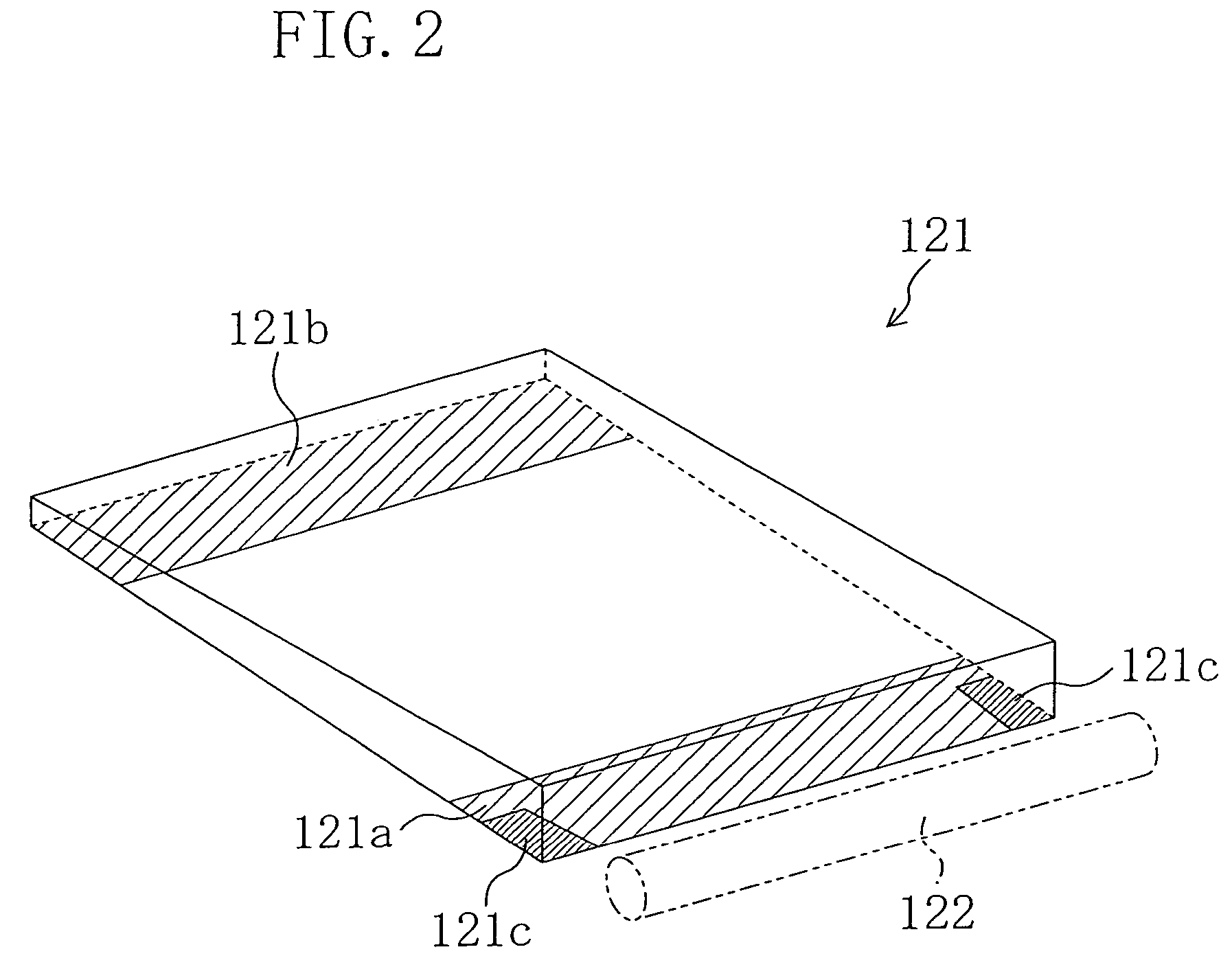
[0045]The backlight 120 has a cuneiform light guide plate 121 made of a transparent acrylic resin (PMMA), for example, and a cold cathode fluorescent lamp 122 is provided at a thicker side of the light guide plate 121. The cold cathode fluorescent lamp 122 is held by a rubber holder 123 for a light source, and a reflection sheet 124 is provided to surround the cold cathode fluorescent lamp 122 and covers a back surface of the light guide plate 121, that is, a non-emission surface of the light guide plate 121. A prism sheet 125 and a diffusio...
second preferred embodiment
[0055]A liquid crystal display according to the second preferred embodiment of the present invention is similar as the first preferred embodiment, except for the structure of the light guide plate 121. The same reference numerals denote the same components as in the first preferred embodiment.
[0056]FIG. 6 is a view showing a surface of the light guide plate 121.
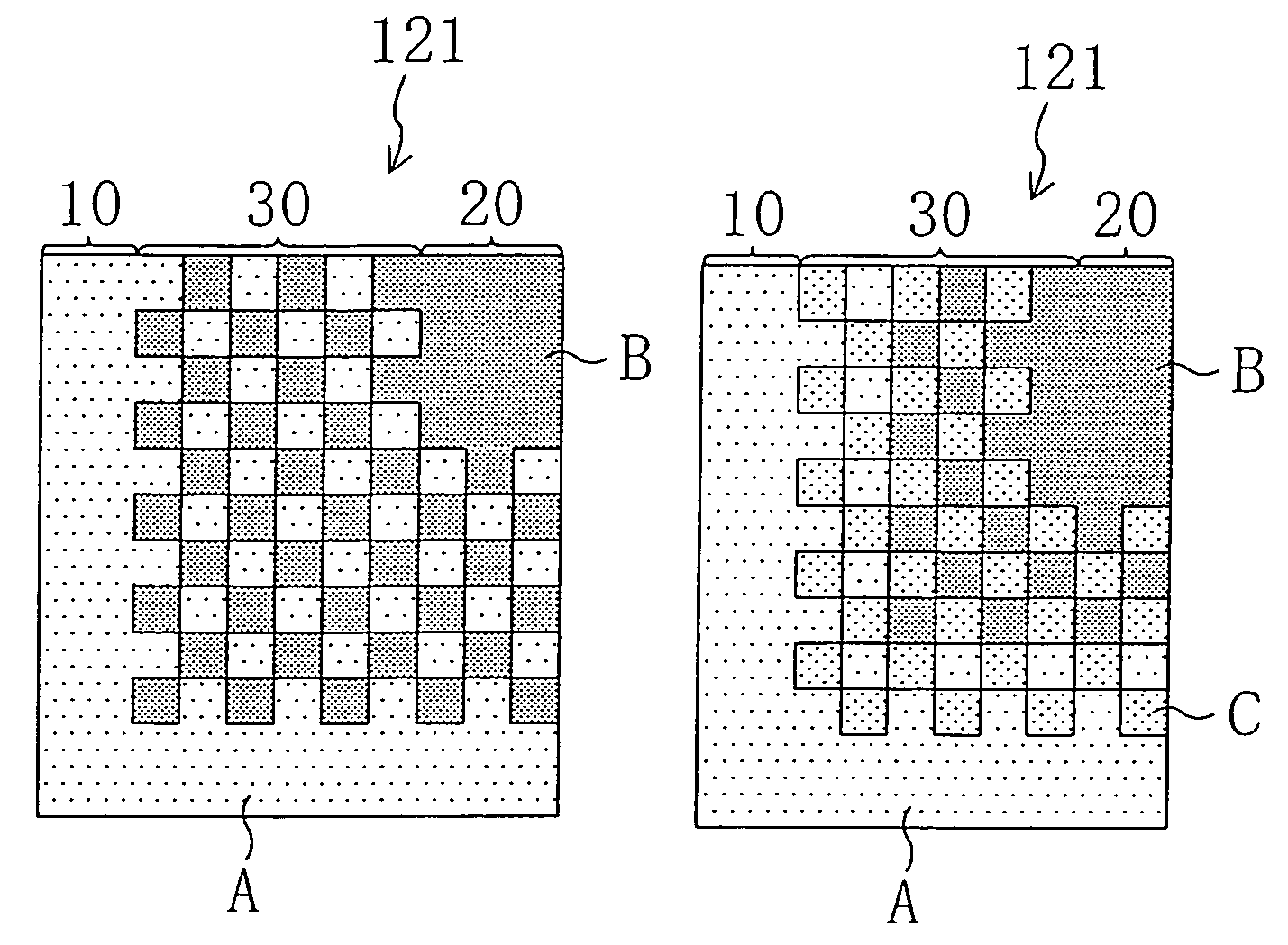
[0057]A boundary-blurring pattern formed by arrangement of a plurality of surface roughness aspects, that is, surface aspects that correspond to the surface roughness formed in a boundary portion 30 between the first region 10 and the second region 20. More specifically, the boundary-blurring pattern is a mosaic pattern of surface roughness aspect A of the first region 10, surface roughness aspect B of the second region 20, and surface roughness aspect C in the middle thereof, in which each element is of about 2 mm to about 3 mm square. Other arrangements and working effects are the same as in the light guide plate 121 in the...
third preferred embodiment
[0059]A liquid crystal display according to third preferred embodiment of the present invention is the same as the first preferred embodiment, except for the structure of the light guide plate 121. The same reference numerals denote the same components as in the first preferred embodiment.
[0060]FIG. 8 is a view showing a surface of the light guide plate 121.
[0061]A boundary-blurring pattern formed of a plurality of surface roughness aspects, that is, surface aspects that correspond to the surface roughness, is located in a boundary portion 30 between a first region 10 and a second region 20. More specifically, the boundary-blurring pattern is a concavo-convex mesh pattern along the boundary portion 30 between the first region 10 and the second region 20. With the concavo-convex mesh pattern, the boundary portion 30 between the first region 10 of a surface roughness aspect A and the second region 20 of a surface roughness aspect B is formed in the shape of rectangle where tine-shaped...
PUM
| Property | Measurement | Unit |
|---|---|---|
| length | aaaaa | aaaaa |
| length | aaaaa | aaaaa |
| width | aaaaa | aaaaa |
Abstract
Description
Claims
Application Information
 - R&D
- Intellectual Property
- Life Sciences
- Materials
- Tech Scout
- Unparalleled Data Quality
- Higher Quality Content
- 60% Fewer Hallucinations
Browse by: Latest US Patents, China's latest patents, Technical Efficacy Thesaurus, Application Domain, Technology Topic, Popular Technical Reports.
© 2025 PatSnap. All rights reserved.Legal|Privacy policy|Modern Slavery Act Transparency Statement|Sitemap|About US| Contact US: help@patsnap.com