Optic fiber LED light source

a technology of optic fiber and led light source, which is applied in the direction of fibre light guide, lighting and heating equipment, instruments, etc., can solve the problems of low light output, not a focused light source, and preventing the application of leds

Active Publication Date: 2007-05-15
EXCELITAS CANADA
View PDF31 Cites 133 Cited by
  • Summary
  • Abstract
  • Description
  • Claims
  • Application Information

AI Technical Summary

Problems solved by technology

However, LEDs are not a focused light source and suffer from relatively low light output.
The lack of focused light and low light output prevents application of LEDs to uses where high light intensity is desired.
Further LEDs cannot be fabricated in different shapes for decorative purposes.
Finally, the light output of LEDs cannot be intensified without an optical device to focus the light.
However neon lighting suffers from a number of problems.
Neon lights require a relatively large amount of electricity resulting in greater costs for applications requiring long term use such as outdoor signs.
Also, neon lights require periodic replacement and maintenance because such lights experience a significant drop off in output after continual use.
All of these factors may create cost issues.
Neon lights require a high voltage transformer which may create safety issues.

Method used


Image

  • Optic fiber LED light source
  • Optic fiber LED light source
  • Optic fiber LED light source

Examples


Embodiment Construction

[0016]While the present invention is capable of embodiment in various forms, there is shown in the drawings and will hereinafter be described a presently preferred embodiment with the understanding that the present disclosure is to be considered as an exemplification of the invention, and is not intended to limit the invention to the specific embodiment illustrated.

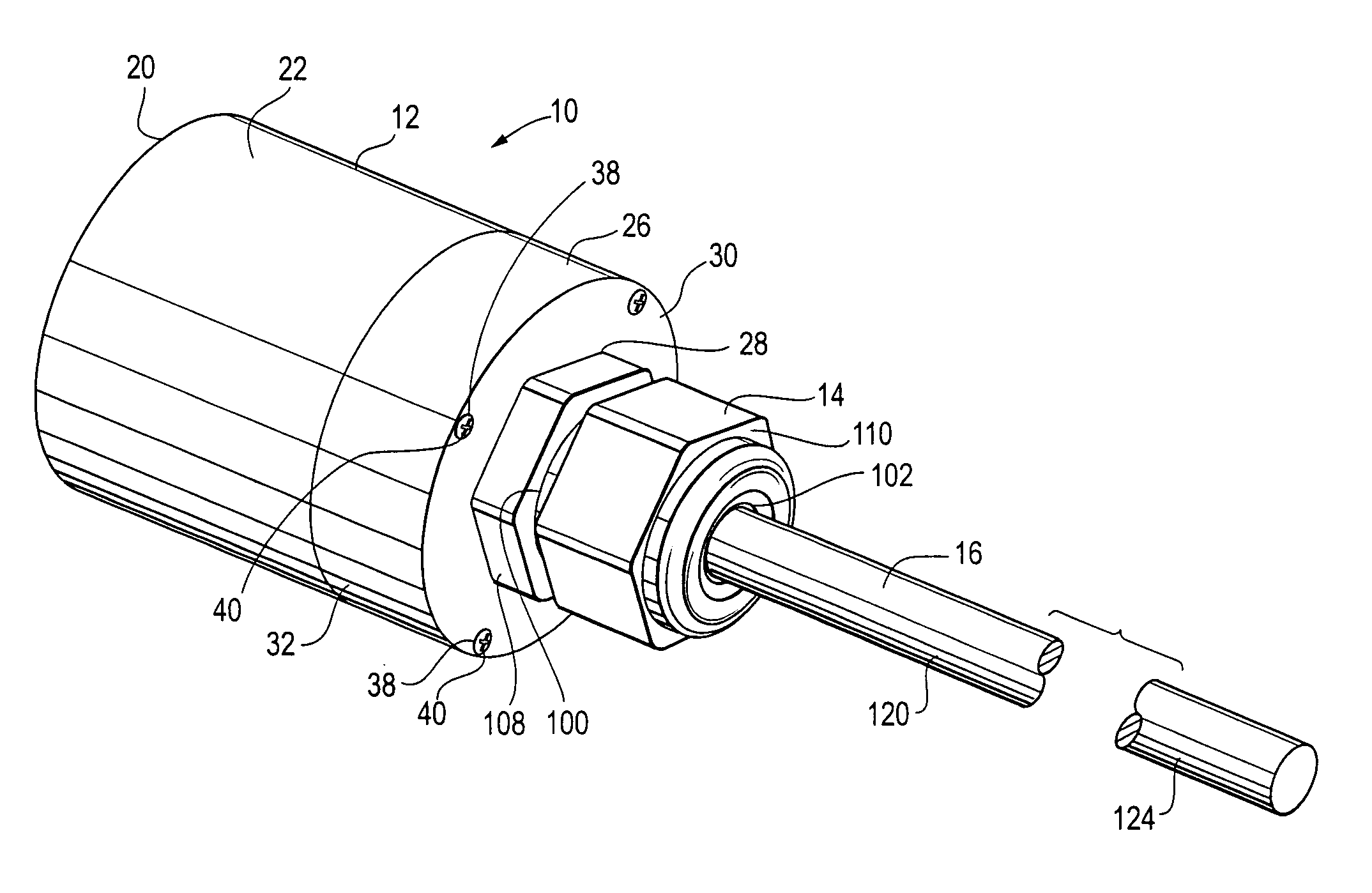
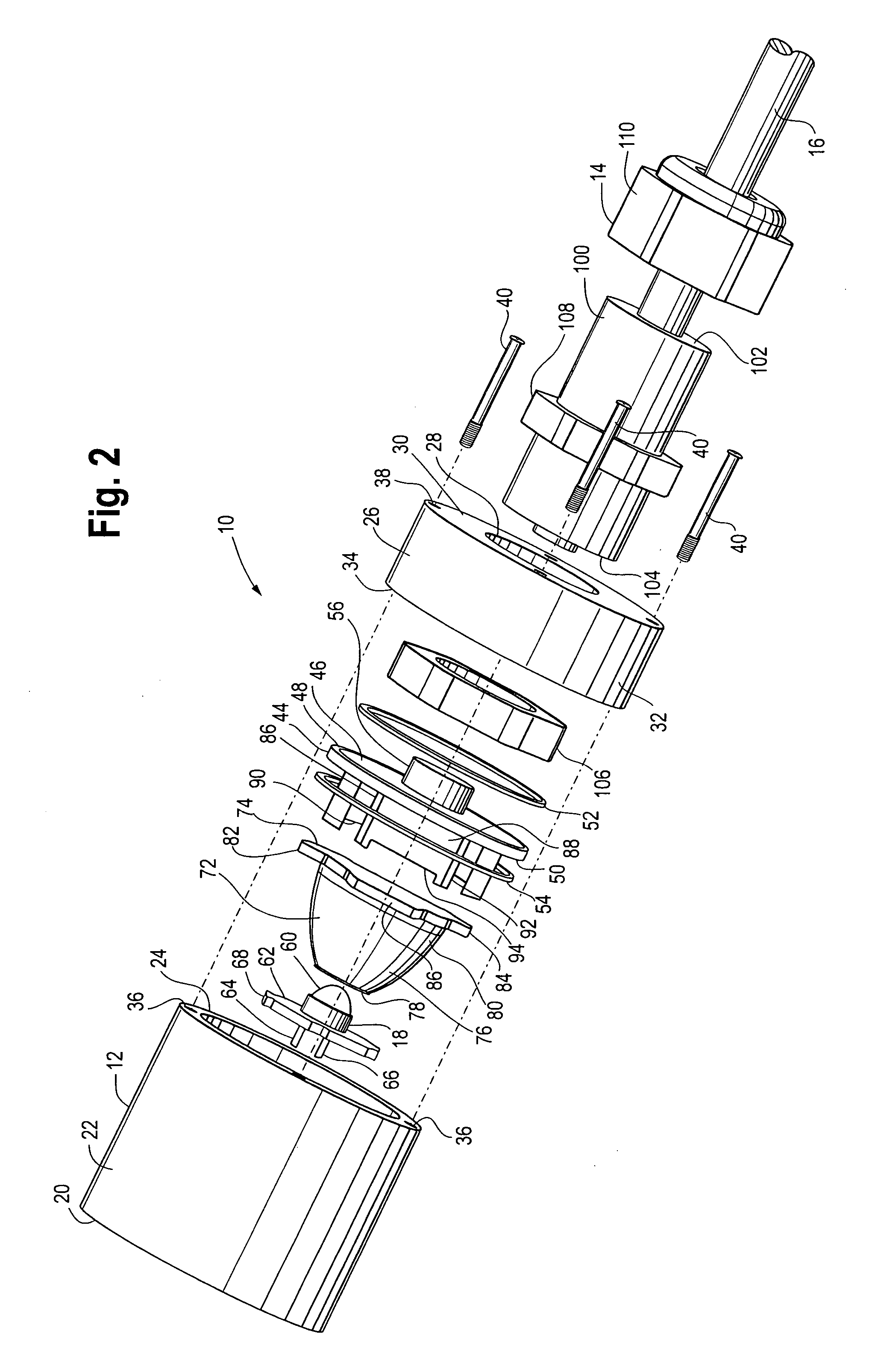
[0017]FIGS. 1–3 show a lighting device 10 which is one example of the present invention. The lighting device 10 is a high output lighting device which is designed for decorative outdoor lighting applications such as signs or architectural highlights. Of course the lighting device 10 may be used for other lighting applications.

[0018]The lighting device 10 has a housing 12, an optic fiber bracket assembly 14 and an optic fiber 16. The housing 12 encloses a lighting assembly 18 which is holds a light emitting diode (LED) as will be explained below. The housing 12 has a closed end with a back plate 20, a circular side wall 22...


PUM


Abstract

An exterior lighting device based on a light emitting diode in conjunction with an optic fiber is disclosed. The device has a cylindrical housing having a closed end and an open end. The light emitting diode is placed on the interior of the on the closed end of the cylindrical housing. A clear lens having one end in proximity with the light emitting diode and an opposite end with a flat surface is provided. A top cap is installed over the open end of the cylindrical housing. The top cap forms a water tight seal with the cylindrical housing using O-rings. A retaining plate is held in place between the top cap and the cylindrical housing. The retaining plate is locked with the flat surface of the lens thus holding the lens in place over the light emitting diode. An optic fiber has a receiving end held by the retaining plate in proximity to the light emitting diode and an opposite emitting end extending from a socket in the top cap. A coupling assembly sits in the socket in the top cap and holds the optic fiber in relation to the top cap.

Description

FIELD OF INVENTION[0001]The present invention relates generally to the field of light emitting diode driven optic fiber lighting devices. More specifically, the present invention is directed to a water resistant optic fiber light emitting diode device which may be used in outdoor lighting applications.BACKGROUND OF INVENTION[0002]Light emitting diodes (LEDs) are well known solid state light sources. LEDs have many advantages over traditional lighting sources such as incandescent bulbs as they are cheaper to produce, more robust, and require less power. LEDs are especially desirable as they emit light with high power efficiency over specific colors in the spectrum. However, LEDs are not a focused light source and suffer from relatively low light output. The lack of focused light and low light output prevents application of LEDs to uses where high light intensity is desired. Further LEDs cannot be fabricated in different shapes for decorative purposes. Finally, the light output of LED...

Claims


Application Information

Patent Timeline
Patent Type & Authority Patents(United States)
IPC IPC(8): F21V8/00
CPCG02B6/0006G02B6/4204
Inventor RUFFIN, MARVIN
Owner EXCELITAS CANADA
Why Eureka
Try Eureka