Pan/tilt/zoom surveillance system and method for dynamically adjusting a user defined image picture mask

a surveillance system and dynamic adjustment technology, applied in the field of surveillance cameras, can solve the problems of lowering the surveillance function and deviating from the privacy mask, and achieve the effect of reducing the calculation error of the mask display

Inactive Publication Date: 2007-05-15
HITACHI INFORMATION & CONTROL SOLUTIONS LTD
View PDF7 Cites 37 Cited by
  • Summary
  • Abstract
  • Description
  • Claims
  • Application Information

AI Technical Summary

Benefits of technology

[0005]It is an object of the present invention to allow the following conventionally-impossible implementations without lowering the surveillance function: Implementing the masking over a privacy-protected range near a location directly below or above the camera's direction, implementing the mask setting-up at a picture edge where the image distortion is large, and implementing a reduction in the calculation error of the mask display caused by a deviation of the camera-mounted position and that of the pan / tilt rotation center.
[0014]In a 2nd embodiment of the surveillance camera according to the present invention, the following configurations are added to those described in the 1st embodiment. This makes it possible to even further enhance the accuracy of the position to be masked, i.e., the object of the present invention.
[0023]In a 3rd embodiment of the surveillance camera according to the present invention, the following configurations are added to those described in the 2nd embodiment. This makes it possible to enhance the accuracy of the position to be masked, i.e., the object of the present invention, higher than the one in the 2nd embodiment.

Problems solved by technology

When setting up the surveillance system like this in public places such as a street, there exists a problem of dealing with such a spot as a private house that is undesirable to be photographed from the viewpoint of the privacy protection.
This eventually masks the portion that need not be masked, thereby lowering the surveillance function.
As a result, there exists a problem that the mask deviates from the privacy mask.

Method used


Image

  • Pan/tilt/zoom surveillance system and method for dynamically adjusting a user defined image picture mask
  • Pan/tilt/zoom surveillance system and method for dynamically adjusting a user defined image picture mask
  • Pan/tilt/zoom surveillance system and method for dynamically adjusting a user defined image picture mask

Examples


Embodiment Construction

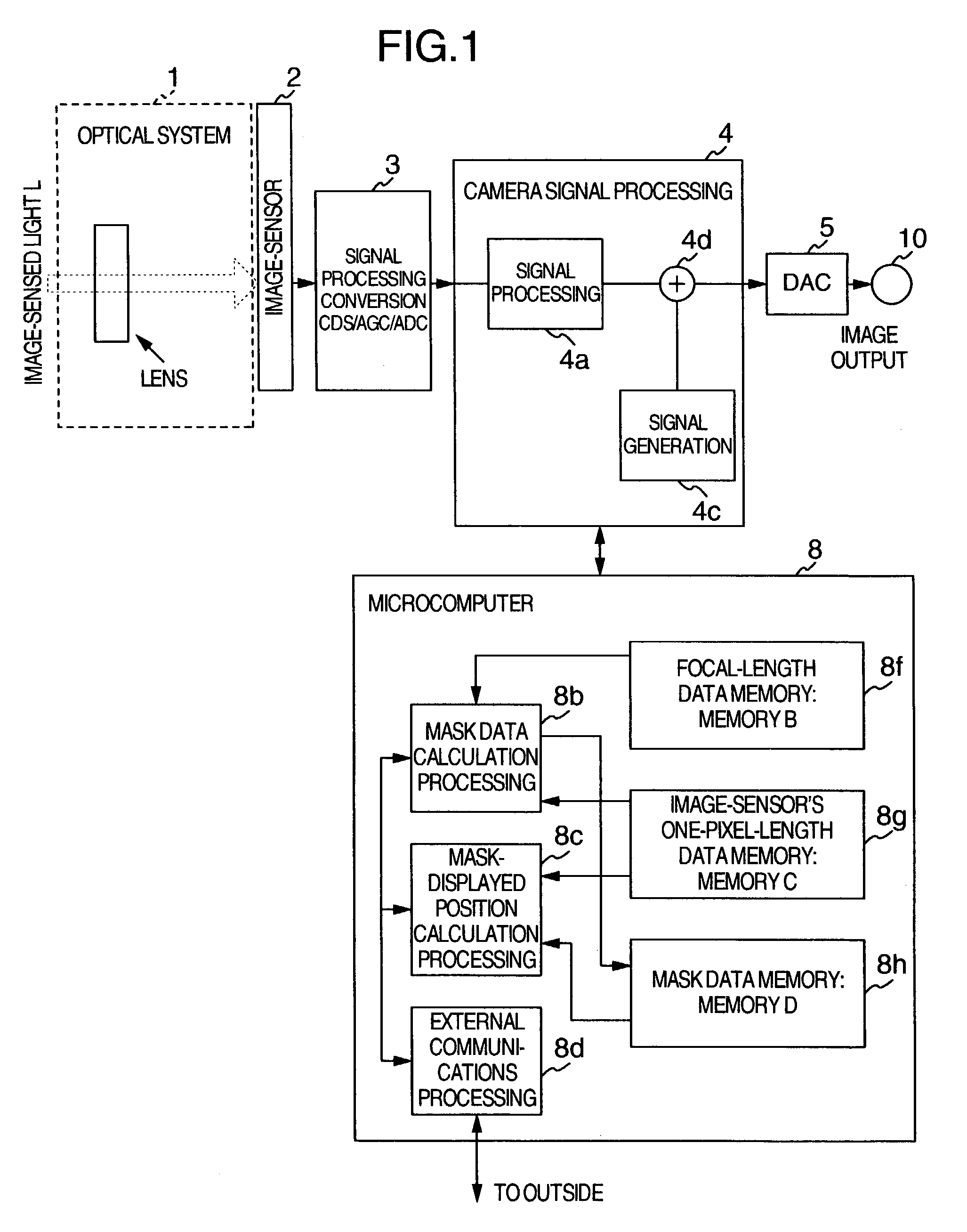
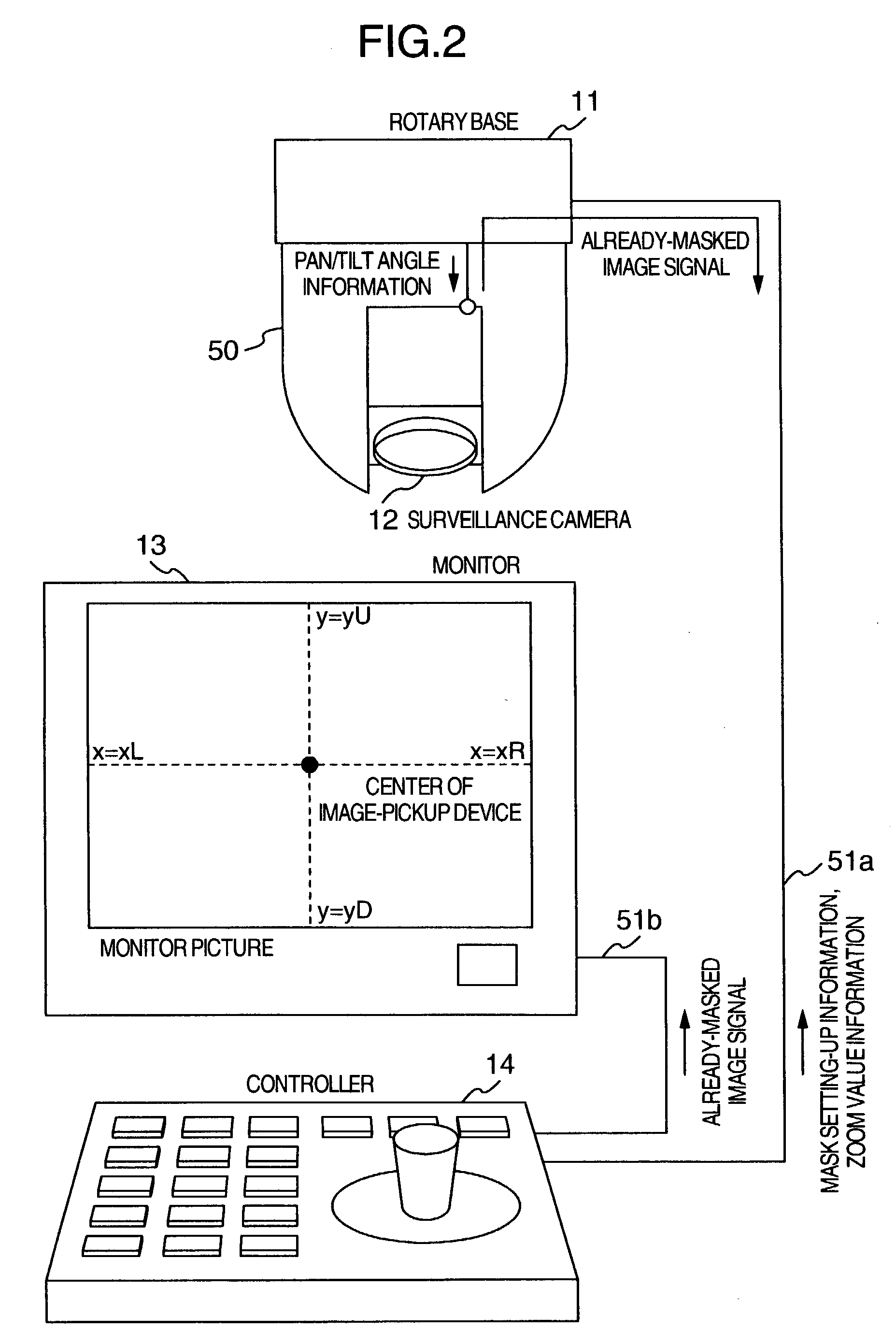
[0050]Hereinafter, the explanation will be given below concerning the embodiments of the present invention. At first, referring to FIG. 1 and FIG. 2, the explanation will be given regarding the 1st embodiment of the present invention. FIG. 1 illustrates the configurations of a surveillance camera 12 according to the 1st embodiment of the present invention. FIG. 2 illustrates a schematic view of a surveillance camera system apparatus as a whole using this surveillance camera 12.

[0051]The surveillance camera 12 illustrated in FIG. 2 is mounted onto a rotary base 11, and is covered with a cover 50. The image signal of a photograph-target is introduced from an image-sensor 2 via an optical lens 1 fixed to an optical system of the surveillance camera 12. Next, the image signal is transmitted to the rotary base 11 and a controller section 14. Here, information needed for the system control, e.g., OSD display of a system control menu or the like, is superimposed on the image signal, then o...


PUM


Abstract

A surveillance camera apparatus includes a first storage unit for storing a size of pixels configuring a image-sensor, a computation unit for performing a computation using first information, second information, third information, and fourth information to calculate angle information on a plurality of vertex-points, the information stored in the first storage unit being defined as the first information, a focal length of an optical lens being defined as the second information, angle information on an optical axis that passes through a rotation center of the surveillance camera apparatus as the third information, and pixel information corresponding to a plurality of vertex-points that form a region to be masked whose image has been picked up by the image-sensor being defined as the fourth information, and a second storage unit for storing the computation result by the computation unit.

Description

BACKGROUND OF THE INVENTION[0001]The present invention relates to a surveillance camera that is mounted onto a for-surveillance-camera rotary base capable of performing a pan (i.e., transverse oscillation) rotation and a tilt (i.e., longitudinal oscillation) rotation. Moreover, the surveillance camera is a one which, in order to protect privacy, includes a mask storage unit and a mask display unit for masking only a privacy-protected range photographed in part of an image.[0002]In the surveillance camera, a video camera is fixed onto the for-surveillance-camera rotary base that is freely rotatable in the pan direction and the tilt direction. This surveillance camera is the following system: An external controller unit operates the for-surveillance-camera rotary base, zooming of the camera, and the like, thereby freely changing an image spot to be photographed by the camera. This surveillance system, in general, includes a sequence function for storing a plurality of image spots so a...

Claims


Application Information

Patent Timeline
Patent Type & Authority Patents(United States)
IPC IPC(8): H04N7/18G06K9/36H04N5/225H04N5/232H04N9/47G06T1/00H04N1/38
CPCG08B13/1963G08B13/1968G08B13/19686H04N7/18
Inventor KOBAYASHI, MITSUNORIKIKUCHI, MAKOTOROKUTA, SHIGEHISA
Owner HITACHI INFORMATION & CONTROL SOLUTIONS LTD
Why Eureka
Try Eureka