Collapsible pallet system and methods

a pallet system and collapsible technology, applied in the field of collapsible pallets, can solve the problems of environmentally “less friendly” staples, nails or other fasteners used in the construction of conventional pallets, and achieve the effects of convenient pallet assembly, convenient transportation and manipulation of components, and convenient pallet delivery

Active Publication Date: 2007-06-19
GORDON NORMAN H
View PDF15 Cites 10 Cited by
  • Summary
  • Abstract
  • Description
  • Claims
  • Application Information

AI Technical Summary

Benefits of technology

[0006]The present invention is directed to a pallet that is easily assembled by a single person without tools and from easily transported and manipulated components. The components can be varied to easily provide pallets of different size and structural dependability. Each of the components for and the assembled pallet is lightweight and uses fewer materials than many pallets made from similar materials. This further reduces waste, lowers shipping costs and ultimately fuel consumption costs associated with the transport of the product shipped on the pallets on the issue of fuel consumption. It has been estimated by the Ford Motor and Automotive Aluminum Association that for every 10 percent reduction in vehicle weight there is a corresponding 6 to 8 percent savings decrease in fuel usage. Comparing an embodiment of the pallet of the present invention to a standard 48×40 inch wood pallet, a savings in fuel usage to carry up to 1200 pounds per truck load (i.e., 30 pounds per pallet savings multiplied by 40 pallets per truck) would result. Less weight means decreased fuel usage and therefore fewer atmospheric emissions. Also, since weight is a factor in road and highway damage, the less weight per truck means less road damage and fewer traffic jams due to highway construction.
[0007]The modular pallet of the present invention is formed from one or more components that can be shipped and stored in a largely flattened state. As a result, prior to assembly, a pallet according to the present invention can take up little space, thereby reducing transportation and storage costs. After formation or assembly, for example, the pallet may be racked into the size permitted by the components, such as a space occupying 4½″×48″×42″.
[0008]The materials from which the pallet components may be made can be “environmentally friendly,” and therefore present low environmental impact. The pallet of the present invention and its components may be formed or joined without the use of metal staples, nails, or other fasteners. The staples, nails or other fasteners used in constructing conventional pallets are typically environmentally “less friendly”. They also may cause harm, such as to a user, when dislodged from the pallet. The use of materials other than wood for the collapsible pallet of the present invention is also economically and environmentally friendly. For example, the use of material other than wood for one or more components of the pallet of the present invention mostly eliminates the need to fumigate the pallet in order to destroy those destructive elements, such as the longhorn beetle that can typically harbor in the wood. In addition, the collapsible pallet of the present invention can be re-used multiple times. Due to the materials used in preferred embodiments of the invention, namely cardboard and like paper-based materials, repairs can be easily made and the present invention contemplates the use of what are termed “repair kits” with the pallets.

Problems solved by technology

The staples, nails or other fasteners used in constructing conventional pallets are typically environmentally “less friendly”.
They also may cause harm, such as to a user, when dislodged from the pallet.

Method used


Image

  • Collapsible pallet system and methods
  • Collapsible pallet system and methods
  • Collapsible pallet system and methods

Examples


Embodiment Construction

[0041]This application incorporates by reference the entire subject matter of U.S. patent application Ser. No. 11 / 118,904, filed Apr. 29, 2005.

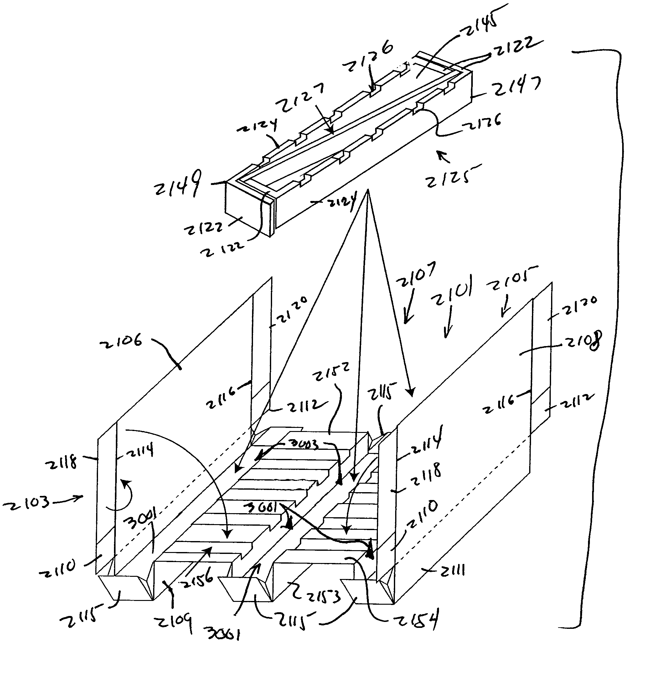
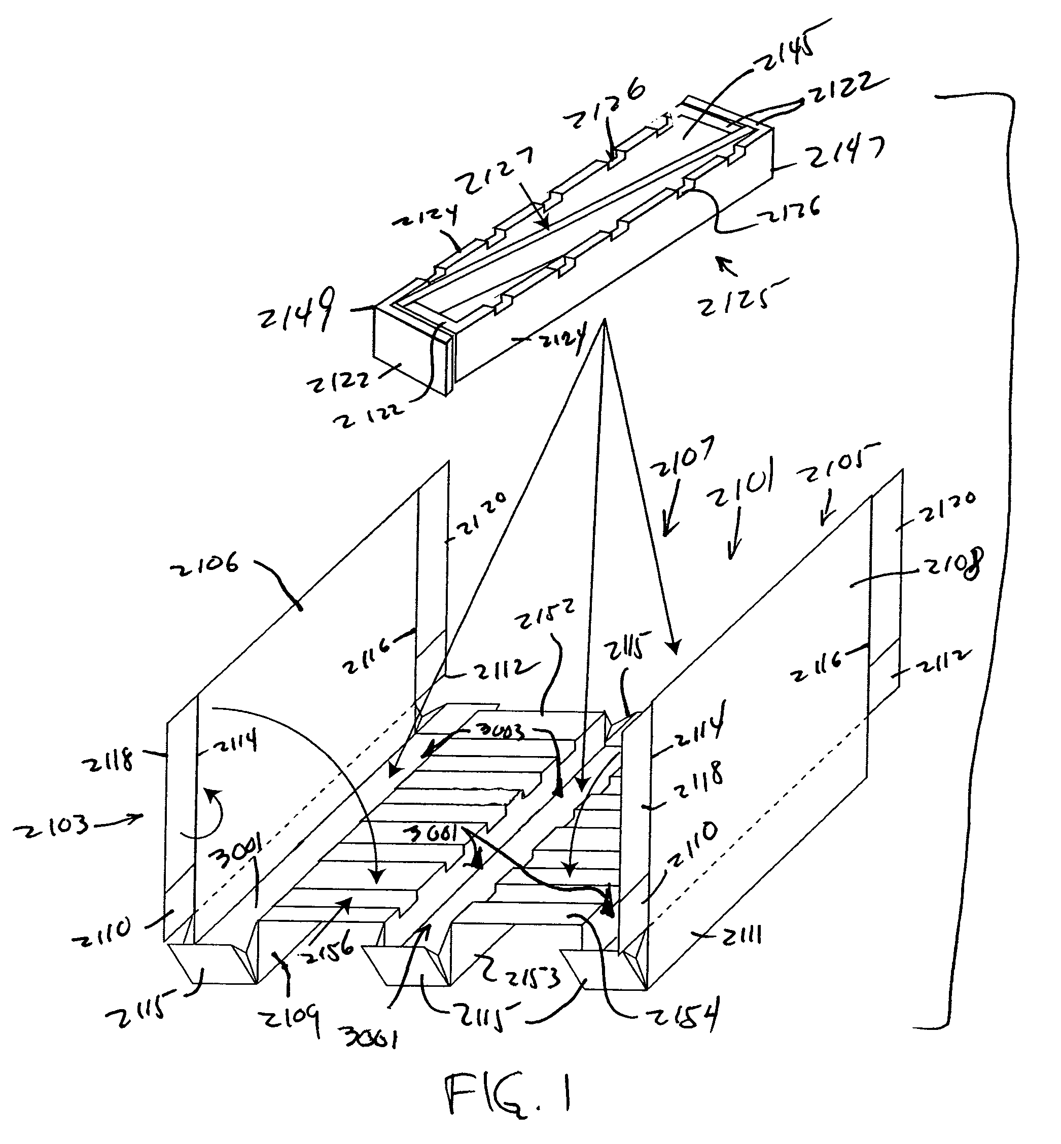
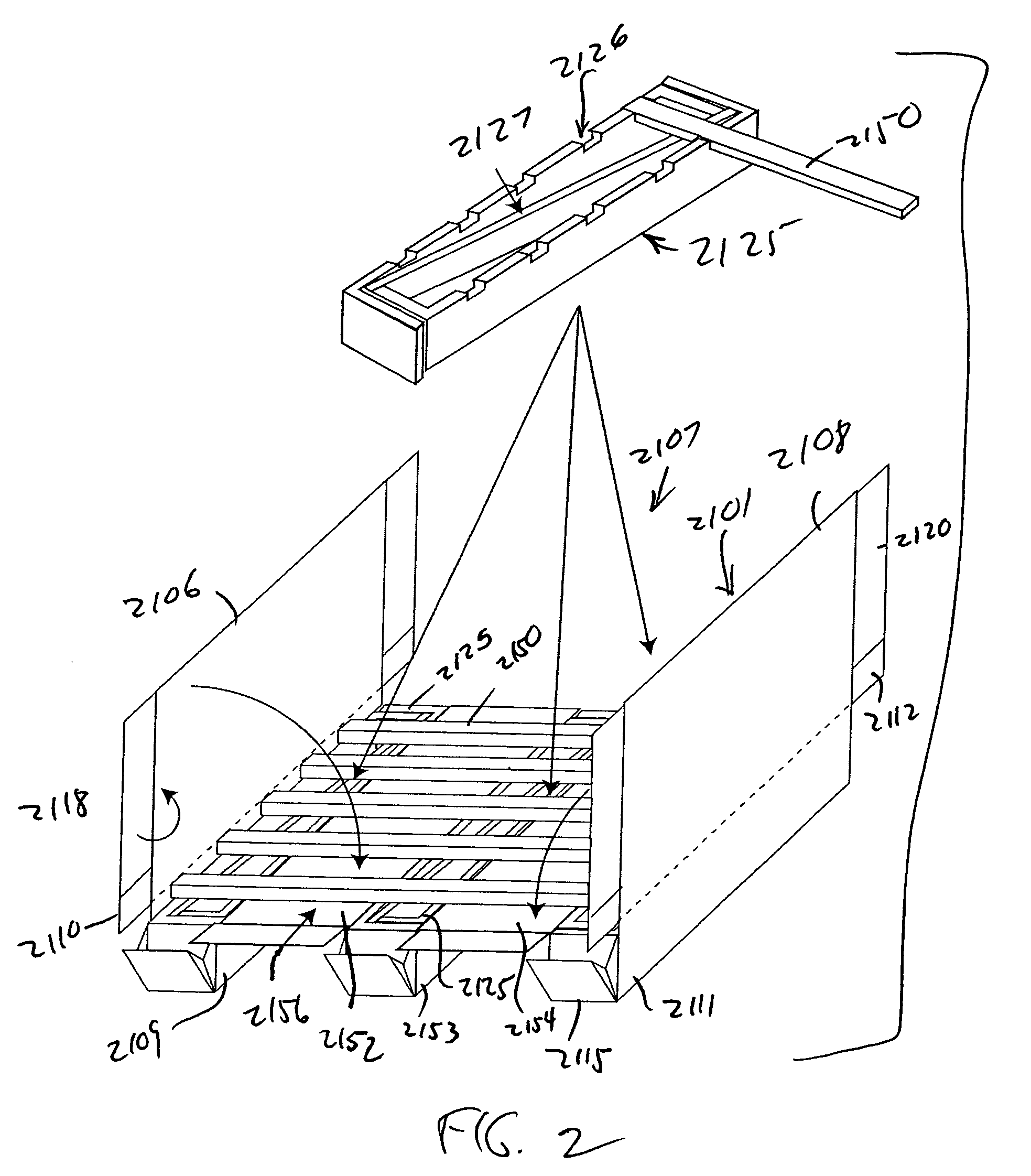
[0042]The present invention will now be described in detail with reference to preferred embodiments as illustrated in the accompanying drawings. In the following description, numerous specific details are set forth in order to provide a thorough understanding of the present invention. It will be apparent, however, to one skilled in the art, that the present invention may be practiced without some or all of these specific details. In other instances, well known process steps and / or structures are not described in detail in order to not unnecessarily obscure the present invention. For convenience of description, terms such as “upper”, “lower”, “top”, “bottom”, “above”, “underneath”, “outer”, “inner”, “horizontal”, “vertical”“outwardly”, and “inwardly” are used to refer to the orientation illustrated in the accompanying drawings. However, it wil...


PUM


Abstract

Formable pallets that are easy to construct into a generally stably product receiving state and easy to collapse into a storage / transport state. Embodiments of the pallet of which include a construction wherein one or more support beams can be further integrally formed from the sheet material of the pallet itself and function to support a product support surface on an uppermost surface of the pallet. The one or more support beams can be supported internally by structural inserts. Additionally, the supporting inserts may include braces for added stability and strength. The beams, as well as the platform can be further braced and structurally supported by cross braces, which run generally at right angles to the beams and pass through apertures in the beams themselves and slots in the inserts.

Description

[0001]This application is a continuation-in-part of U.S. patent application Ser. No. 11 / 118,904, filed Apr. 29, 2005; which claims the benefit of U.S. Provisional Application No. 60 / 566,256 filed Apr. 29, 2004; U.S. Provisional Application No. 60 / 632,554 filed Dec. 1, 2004; and U.S. Provisional Application No. 60 / 652,871 filed Feb. 15, 2005.FIELD OF THE INVENTION[0002]The present invention relates to a collapsible pallet and more specifically to a pallet formed from a sheet material.BACKGROUND OF THE INVENTION[0003]Pallets are platforms for supporting weight thereon, and by which materials, packages, or goods that are stacked thereon may be handled, stored and / or moved. Goods positioned on pallets are typically moved and stored in warehouses, factories, or vehicles, for example, by forklift equipment, in which the forklift tines are inserted into channels in the pallet or by way of engagement with an undersurface of a top deck of the pallet.[0004]Pallets have traditionally been form...

Claims


Application Information

Patent Timeline
Patent Type & Authority Patents(United States)
IPC IPC(8): B65D19/00
CPCB65D19/0016B65D77/003B65D81/107B65D2203/10B65D2519/00019B65D2519/00034B65D2519/00054B65D2519/00069B65D2519/00129B65D2519/00134B65D2519/00139B65D2519/00268B65D2519/00273B65D2519/00288B65D2519/00293B65D2519/00298B65D2519/00318B65D2519/00323B65D2519/00333B65D2519/00338B65D2519/00343B65D2519/00437B65D2519/00442B65D2519/00562B65D2519/00567B65D2519/00751B65D2519/0086B65D2519/0087B65D2519/0098
Inventor GORDON, NORMAN H.
Owner GORDON NORMAN H
Why Eureka
Try Eureka