Reactant gas humidification apparatus and reactant gas humidification method

a technology of reactant gas and humidification apparatus, which is applied in the direction of lighting and heating apparatus, heating types, and separation processes, etc. it can solve the problems of large space required for installation of humidification apparatus, inability to efficiently humidify the entire air, and inability to mount the large humidification apparatus in a vehicle. , to achieve the effect of reducing the overall size of the humidification apparatus and efficient and reliably humidifying the reactant gases

Active Publication Date: 2007-08-21
HONDA MOTOR CO LTD
View PDF13 Cites 15 Cited by
  • Summary
  • Abstract
  • Description
  • Claims
  • Application Information

AI Technical Summary

Benefits of technology

[0012]A general object of the present invention is to provide a reactant gas humidification apparatus and a reactant gas humidification method which make it possible to efficiently and reliably humidify reactant gases, and achieve reduction in the overall size of the humidification apparatus easily.
[0013]A main object of the present invention is to provide a reactant gas humidification apparatus which makes it possible to maintain the pressure applied to the surface of a seal to achieve improvement in the sealing performance, and maintain the suitable rigidity in the stacking direction.
[0024]Preferably, the seal width of the seal is smaller than the width of the straight ridge. Thus, since the rigid first and second separators contact each other, the water permeable membrane is sandwiched between the first and second separators reliably, and improvement in the rigidity in the stacking direction is achieved. Further, since sealing is carried out at the straight ridge which is outside the vapor permeable surface, in the surfaces of the first and second separators, it is possible to efficiently increase the effective surface area used for permeation of the vapor.
[0025]Preferably, the flow direction of the first flow grooves where the seal is provided intersects with the flow direction of the second flow grooves in an area of the straight ridge. Preferably, the seal is provided in an area of the first flow grooves. Thus, in the surfaces of the first and second separators, it is possible to efficiently increase the effective surface area used for permeation of the vapor, and improvement in the vapor permeability is achieved easily.
[0028]According to the present invention, the first flow field and the second flow field are provided at least on the first surface and the second surface of the first separator for supplying the same reactant gas or the same humidification fluid to achieve suitable humidification of the reactant gas. Thus, it is possible to effectively and reliably humidify the reactant gas, and reduce the overall size of the humidification apparatus easily.
[0029]Further, according to the present invention, the seal of the first separator is overlapped with the flat surface of the straight ridge of the second separator. Therefore, the seal is reliably supported by the straight ridge. With the simple structure, the pressure applied to the surface of the seal is maintained, improvement in the sealing performance is achieved, and the suitable rigidity in the stacking direction is maintained. Further, the entire sealing surface is the flat, and does not include any step. In particular, for example, it is possible to prevent the increase of the pressure loss due to deformation of the water permeable membrane or leakage due to the deformation of the seal.

Problems solved by technology

Therefore, it is not possible to efficiently humidify the entire air before reaction flowing through the humidification outbound flow field 3 by the water in the off gas flowing through the humidification inbound flow field 4.
Thus, a large space is required for installation of the humidification apparatus.
For example, it is not possible to mount the large humidification apparatus in a vehicle.
Thus, the desired sealing performance cannot be maintained.
Further, the rigidity in the stacking direction may be lowered disadvantageously.

Method used


Image

  • Reactant gas humidification apparatus and reactant gas humidification method
  • Reactant gas humidification apparatus and reactant gas humidification method
  • Reactant gas humidification apparatus and reactant gas humidification method

Examples


first embodiment

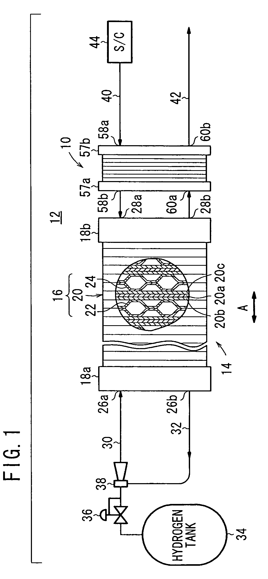
[0052]FIG. 1 is a view schematically showing structure of a fuel cell system 12 including a humidification apparatus 10 according to the present invention.

[0053]For example, the fuel cell system 12 is mounted in a vehicle such as an automobile, and includes a fuel cell stack 14. The fuel cell stack 14 includes a plurality of power generation cells (solid polymer electrolyte fuel cells) 16 stacked in a direction indicated by an arrow A. At opposite ends of the power generation cells 16 in stacking direction, end plates 18a, 18b are provided. The end plates 18a, 18b are tightened together in the stacking direction using tightening bolts (not shown).

[0054]For example, the power generation cell 16 includes a membrane electrode assembly 20 and a pair of separators 22, 24 sandwiching the membrane electrode assembly 20. The membrane electrode assembly 20 includes an anode 20b, a cathode 20c, and a solid polymer electrolyte membrane 20a interposed between the anode 20b and the cathode 20c. ...

third embodiment

[0108]FIG. 10 is an exploded perspective view showing main components of a humidification apparatus 130 according to the present invention.

[0109]The humidification apparatus 130 includes a first separator 132 and a second separator 134 which are provided alternately on one surface 50a of the water permeable membrane 50 and the other surface 50b of the water permeable membrane 50.

[0110]The first separator 132 has a first flow field 136 on a first surface 132a facing one surface 50a of the water permeable membrane 50. The first flow field 136 includes a plurality of grooves 136a in a serpentine pattern having three turn regions and four straight regions for allowing the air to flow back and forth indicated by the arrow B. The serpentine grooves 136a of the first flow field 136 are connected between the air supply passage 58a and the air discharge passage 58b. Further, the first separator 132 has a second flow field 138 on a second surface 132b opposite to the first surface 132a. The s...

fourth embodiment

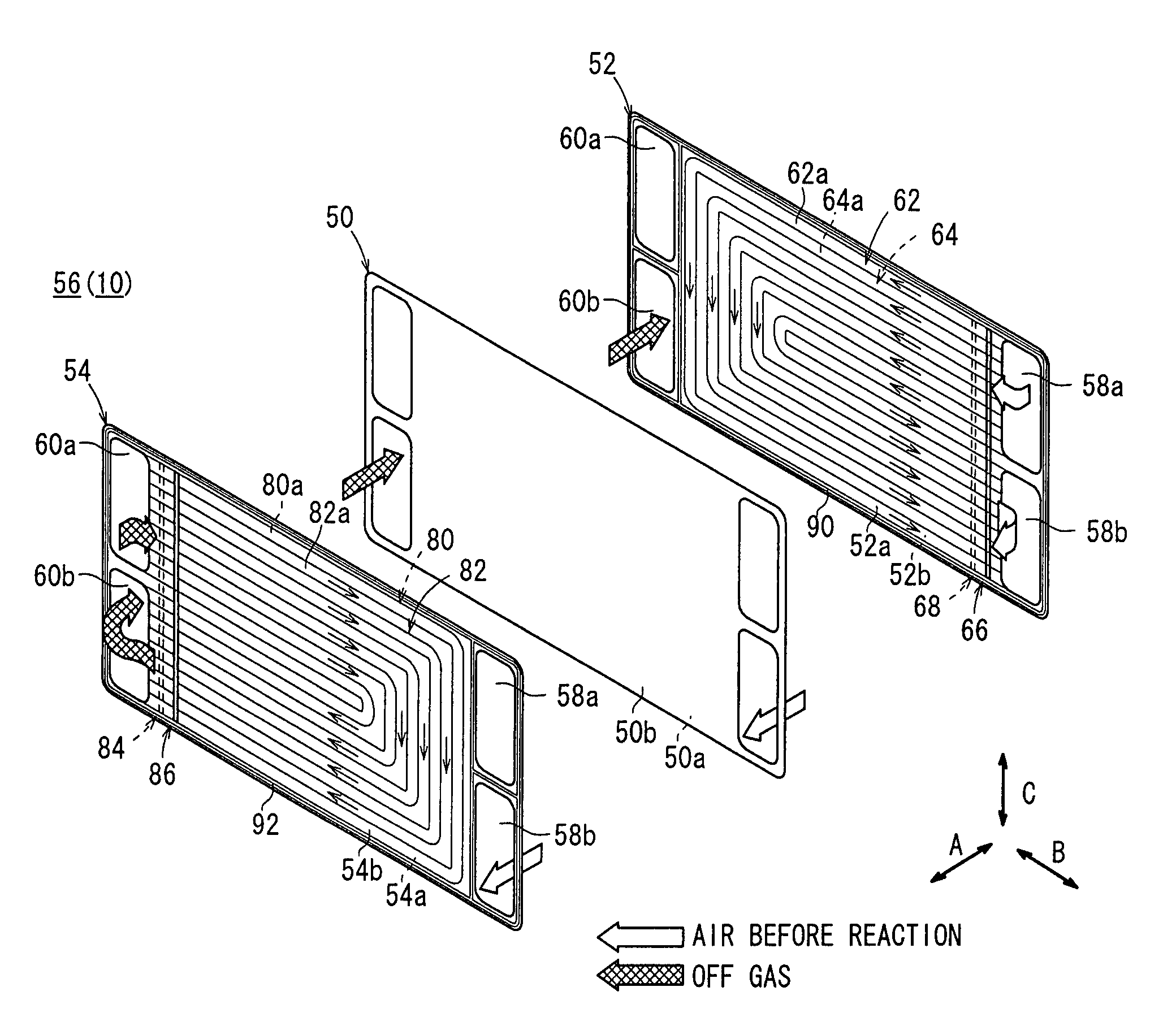
[0114]FIG. 11 is an exploded perspective view showing main components of a humidification apparatus 160 according to the present invention.

[0115]The humidification apparatus 160 includes a first separator 162 and a second separator 164 which are provided alternately on one surface 50a of the water permeable membrane 50 and the other surface 50b of the water permeable membrane 50.

[0116]The first separator 162 has a first flow field 166 on a first surface 162a and a second flow field 168 on a second surface 162b. The first flow field 166 includes a plurality of straight grooves 166a extending in the direction indicated by the arrow B. The straight grooves 166a are connected between the air supply passage 58a and the air discharge passage 58b. The second flow field 168 includes a plurality of straight grooves 168a extending in the direction indicated by the arrow B. The straight grooves 168a are connected between the air supply passage 58a and the air discharge passage 58b. The grooves...


PUM


Abstract

A reactant gas humidification apparatus includes a first separator provided on one surface of a water permeable membrane and a second separator provided on the other surface of the water permeable membrane. The first separator has first and second flow fields on both surfaces for supplying an air before reaction as the same reactant gas. Further, the second separator has third and fourth flow fields on both surfaces for supplying an off gas as the same humidifying fluid. The off gas is used for humidifying the air before reaction.

Description

BACKGROUND OF THE INVENTION[0001]1. Field of the Invention[0002]The present invention relates to a reactant gas humidification apparatus and a reactant gas humidification method in which a reactant gas is supplied to one surface of a water permeable membrane, and a humidifying fluid is supplied to the other surface of the water permeable membrane for humidifying the reactant gas.[0003]2. Description of the Related Art[0004]For example, a solid polymer electrolyte fuel cell employs a membrane electrode assembly (MEA) which includes two electrodes (anode and cathode), and an electrolyte membrane interposed between the electrodes. The electrolyte membrane is a polymer ion exchange membrane. The membrane electrode assembly is interposed between a pair of separators. The membrane electrode assembly and the separators make up a power generation cell for generating electricity. In use, a plurality of the power generation cells are stacked together to form a fuel cell stack.[0005]In the fue...

Claims


Application Information

Patent Timeline
Patent Type & Authority Patents(United States)
IPC IPC(8): B01F3/04H01M8/02H01M8/04H01M8/10
CPCH01M8/02H01M8/04141H01M8/04149H01M2008/1095Y02E60/50
Inventor SASAMOTO, KAZUYA
Owner HONDA MOTOR CO LTD
Why Eureka
Try Eureka