Interface card coupling structure

a technology of coupling structure and interface card, which is applied in the direction of coupling device connection, electrical apparatus casing/cabinet/drawer, instruments, etc., can solve the problems of high cost, easy loosening or breaking of interface cards from the insertion slots, and inability to be economical, so as to reduce cost, increase production, and simplify the structure

Inactive Publication Date: 2007-09-18
INVENTEC CORP
View PDF6 Cites 5 Cited by
  • Summary
  • Abstract
  • Description
  • Claims
  • Application Information

AI Technical Summary

Benefits of technology

[0004]In view of the aforesaid problems, the primary object of the invention is to provide an interface card coupling structure that has a simplified structure to increase production and reduce cost.
[0008]In the structure set forth above, the coupling member may be made by injection forming to simplify elements, reduce cost, and increase production.

Problems solved by technology

When used for a prolonged period of time in an environment where vibrations occur or moving happens frequently, the interface cards are prone to loosen or break away from the insertion slots (not shown in the drawings).
All this requires many elements and results in a higher cost.
This is not economical, especially in today's business environment where the profit margin is small and competition is fierce.

Method used


Image

  • Interface card coupling structure
  • Interface card coupling structure
  • Interface card coupling structure

Examples


Embodiment Construction

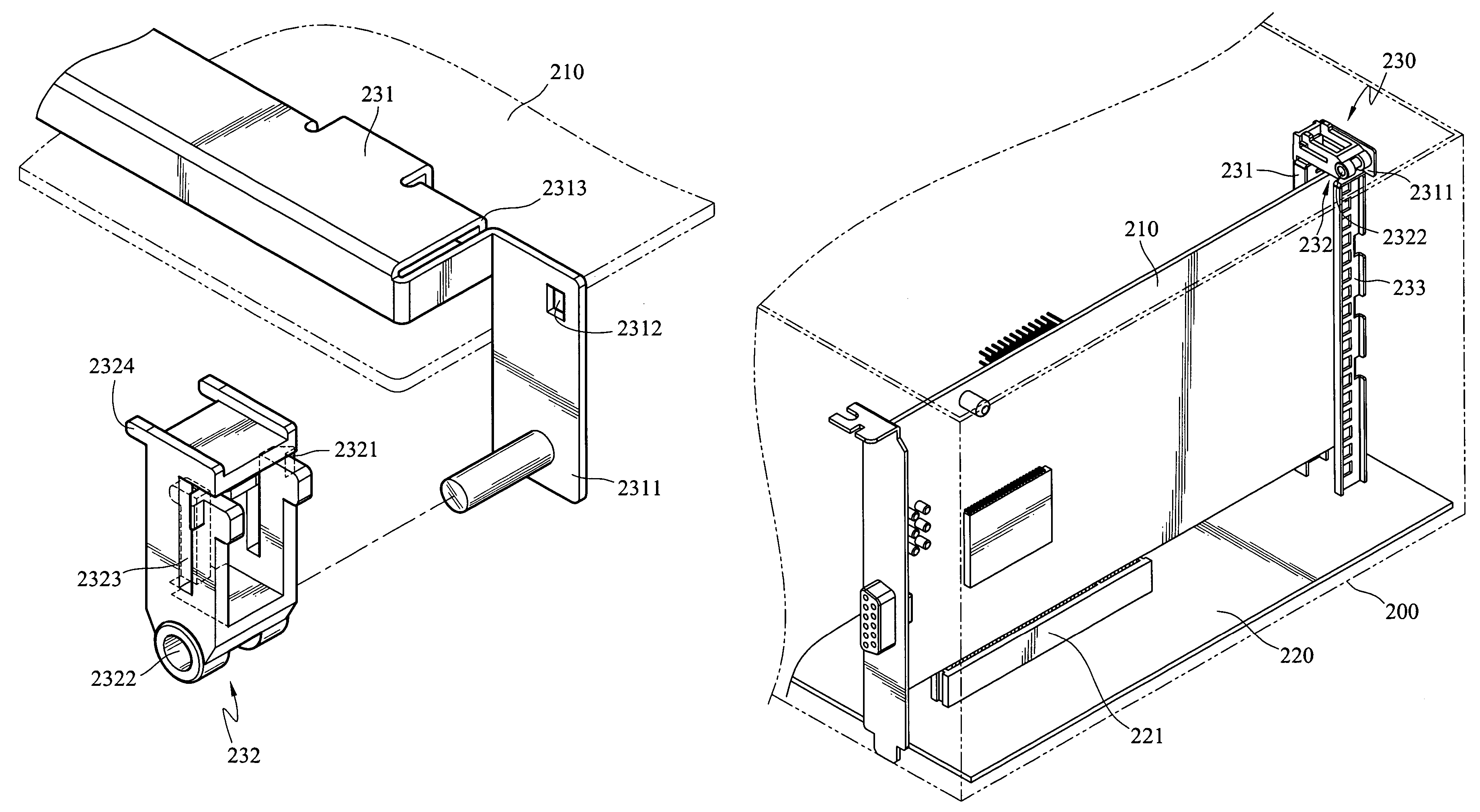
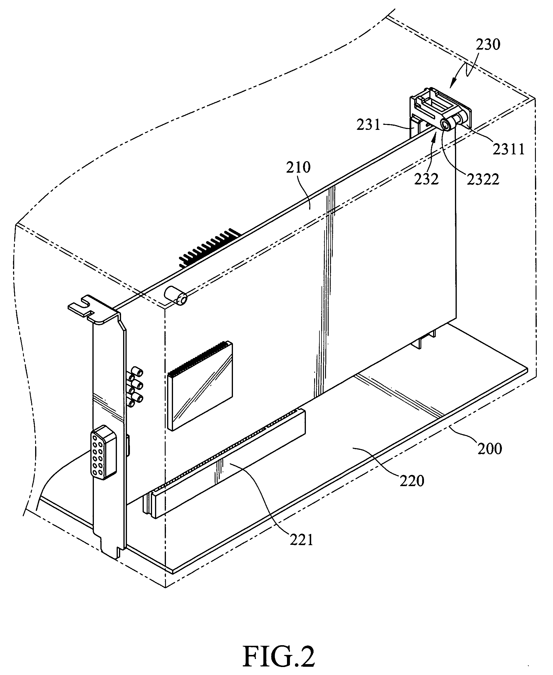
[0016]Referring to FIG. 2, the interface coupling structure 230 according to the invention is fixedly mounted onto a case 200, which houses an interface card 210 and a mainboard 220. The interface coupling structure 230 aims to securely couple the interface card 210 on the mainboard 220. The interface coupling structure 230 includes a bracing member 231 and a coupling member 232. Details of their structure and coupling relationship are elaborated as follows.

[0017]Referring to FIGS. 3 and 4, the bracing member 231 is fixedly located on the case 200. It has a retaining plate 2311 extending from one end. The retaining member 2311 has a latch hole 2312. The bracing member 231 further has a notch 2313 on the end where the retaining plate 2311 is located. The notch 2313 is located on the edge of the bracing member 231 and is formed substantially in a step manner. The coupling member 232 aims to latch the interface card 210 to prevent the interface card 210 from breaking away from the main...


PUM


Abstract

An interface card coupling structure includes a bracing member fastened to a case that has a retaining plate extending from an edge with a latch hole formed thereon, and a coupling member pivotally coupled on the retaining plate. The coupling member has a latch pin on one end facing the retaining plate to engage with the latch hole and anchor the coupling member on the retaining plate. The coupling member presses an interface card to form secure coupling. The coupling member may be made by injection forming. The structural elements of the bracing member of the interface card coupling structure are thus fewer. Hence the cost may be reduced and production speed increased.

Description

FIELD OF THE INVENTION[0001]The invention relates to a coupling structure, and particularly to an interface card coupling structure to anchor an interface card on a mainboard with a reinforced coupling.BACKGROUND OF THE INVENTION[0002]A typical computer is coupled with many interface cards. This is especially true for larger computers or industrial computers for which there are many types of interface cards. When used for a prolonged period of time in an environment where vibrations occur or moving happens frequently, the interface cards are prone to loosen or break away from the insertion slots (not shown in the drawings). To prevent the interface card from breaking away from the insertion slot, a coupling structure is usually used to anchor one end of the interface card as shown in FIG. 1. Such a coupling structure generally includes a bracing member 100, which has a retaining plate 101 and a coupling plate 102 extended from one end. The retaining plate 101 and the coupling plate ...

Claims


Application Information

Patent Timeline
Patent Type & Authority Patents(United States)
IPC IPC(8): H05K7/12
CPCG06F1/185G06F1/186H05K7/1405
Inventor CHANG, LIN-WEI
Owner INVENTEC CORP
Why Eureka
Try Eureka