Eye refractive power measurement device

a technology of refractive power and measurement device, which is applied in the field of eye refractive power measurement device, can solve the problems of compound device difficulty, increased size and cost in comparison with a known device, and inability to obtain high-frequency components, etc., and achieves the effect of preventing an increase in size and cost and being convenient for the operator

Active Publication Date: 2007-11-06
RIGHT MFG
View PDF4 Cites 13 Cited by
  • Summary
  • Abstract
  • Description
  • Claims
  • Application Information

AI Technical Summary

Benefits of technology

[0010]An objective of the present invention is to provide a compound device having an eye refractive power measurement function and an eye accommodation function state measurement function, preventing an increase in size and cost in comparison with a known eye refractive power measurement device, and convenient for the operator even when the measurement type is changed.
[0019]According to the present invention, a compound device having an eye refractive power measurement function and an eye accommodation function state measurement function can be provided which prevents an increase in size and cost in comparison with a known eye refractive power measurement device and is convenient for the operator even when the measurement type is changed.

Problems solved by technology

And in the meantime the high-frequency components cannot to be obtained unless the measurements are continuously performed.
Therefore, since it is difficult to directly apply a known eye refractive power measurement device to an eye accommodation function state measurement device, an eye refractive power measurement device must be improved or modified so that continuous measurement can be performed at higher speed.
This results in an increase in size and cost in comparison with a known device.
A compound device may suffer from a display difficulty if the normal refractive power measurement is performed at high speed in the same manner as the eye accommodation function state measurement device.

Method used


Image

  • Eye refractive power measurement device
  • Eye refractive power measurement device
  • Eye refractive power measurement device

Examples


first embodiment

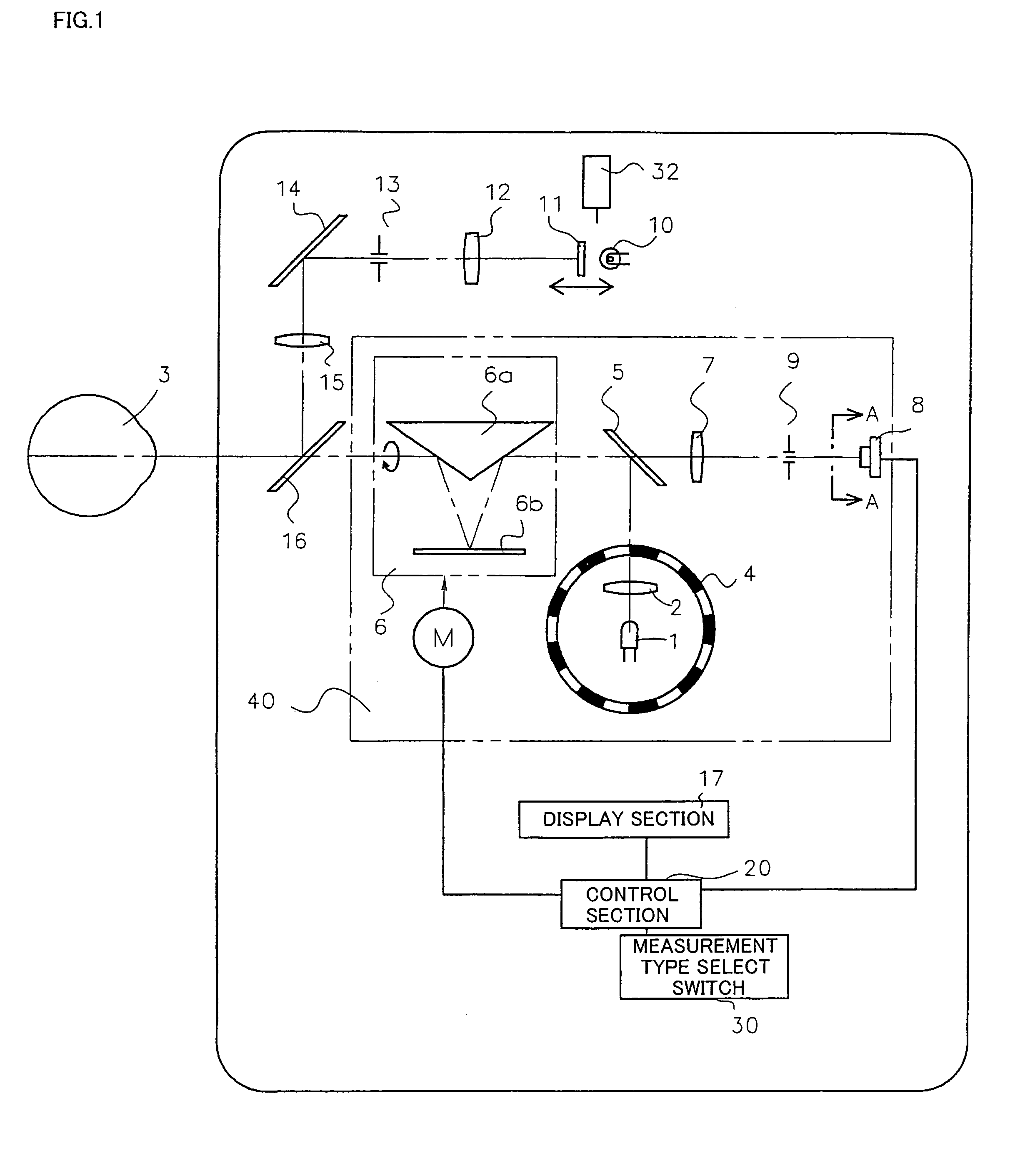
[0027]FIG. 1 is a diagram showing a configuration of an optical system of an eye refractive power measurement device according to a first embodiment of the present invention.

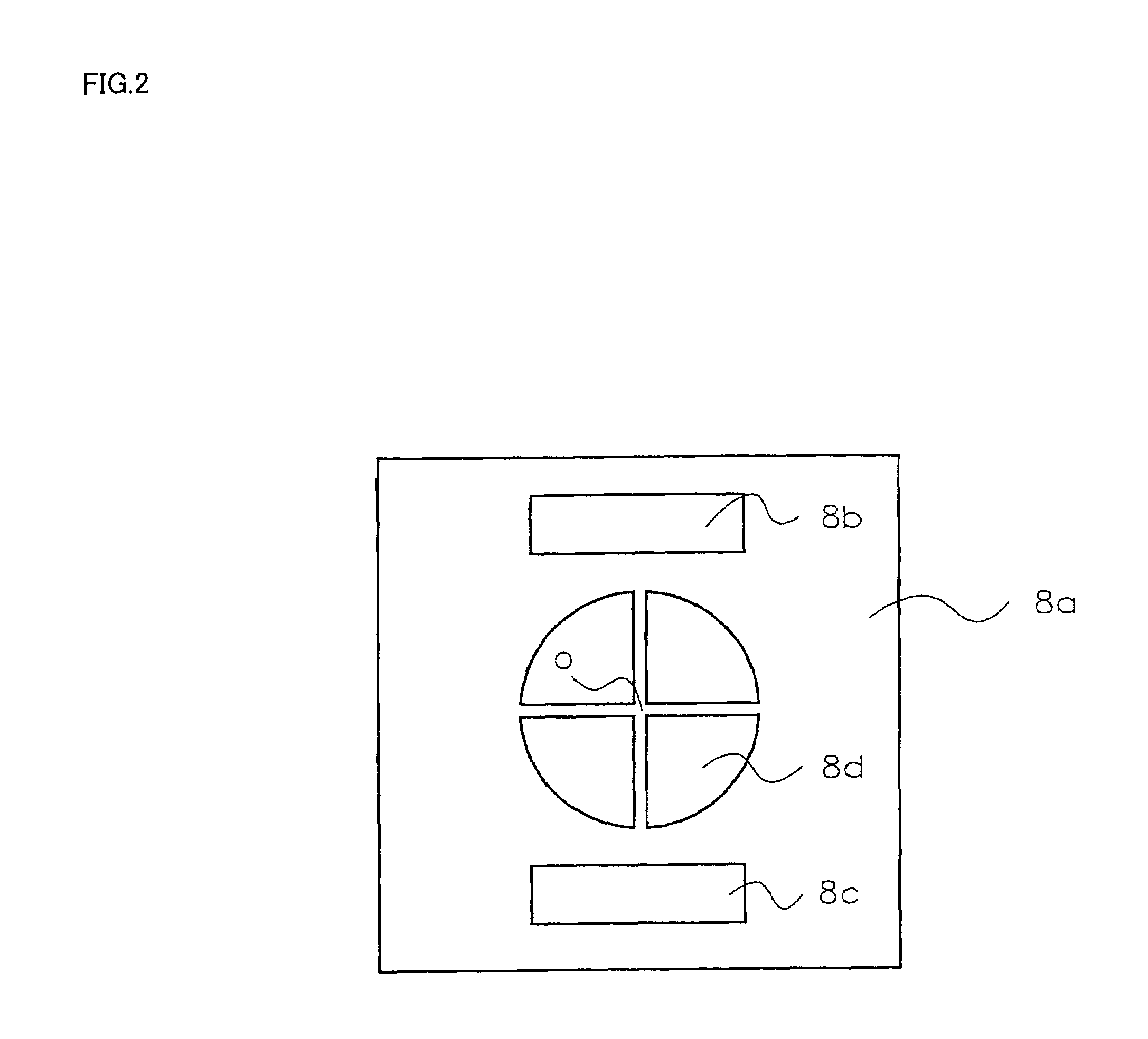
[0028]FIG. 2 is a diagram showing a photoelectric conversion element 8 used in the first embodiment viewed along the line A-A shown in FIG. 1.

[0029]The eye refractive power measurement device according to the first embodiment includes a refractive power measurement section 40 and a fogging device. The measurement principle of the refractive power measurement section 40 is retinoscopy, in which the eye refractive power is measured by detecting the moving speed of a shadow on the pupil. An objective eye refractive power measurement device using retinoscopy is disclosed in JP-A-55-86437, for example. The configuration of the device used in the present invention is basically the same as that of the device disclosed in JP-A-55-86437. Therefore, description of the details of the measurement principle is omitted.

[0030]...

second embodiment

[0045]A second embodiment of the present invention is described below with reference to FIGS. 4, 5, and 6.

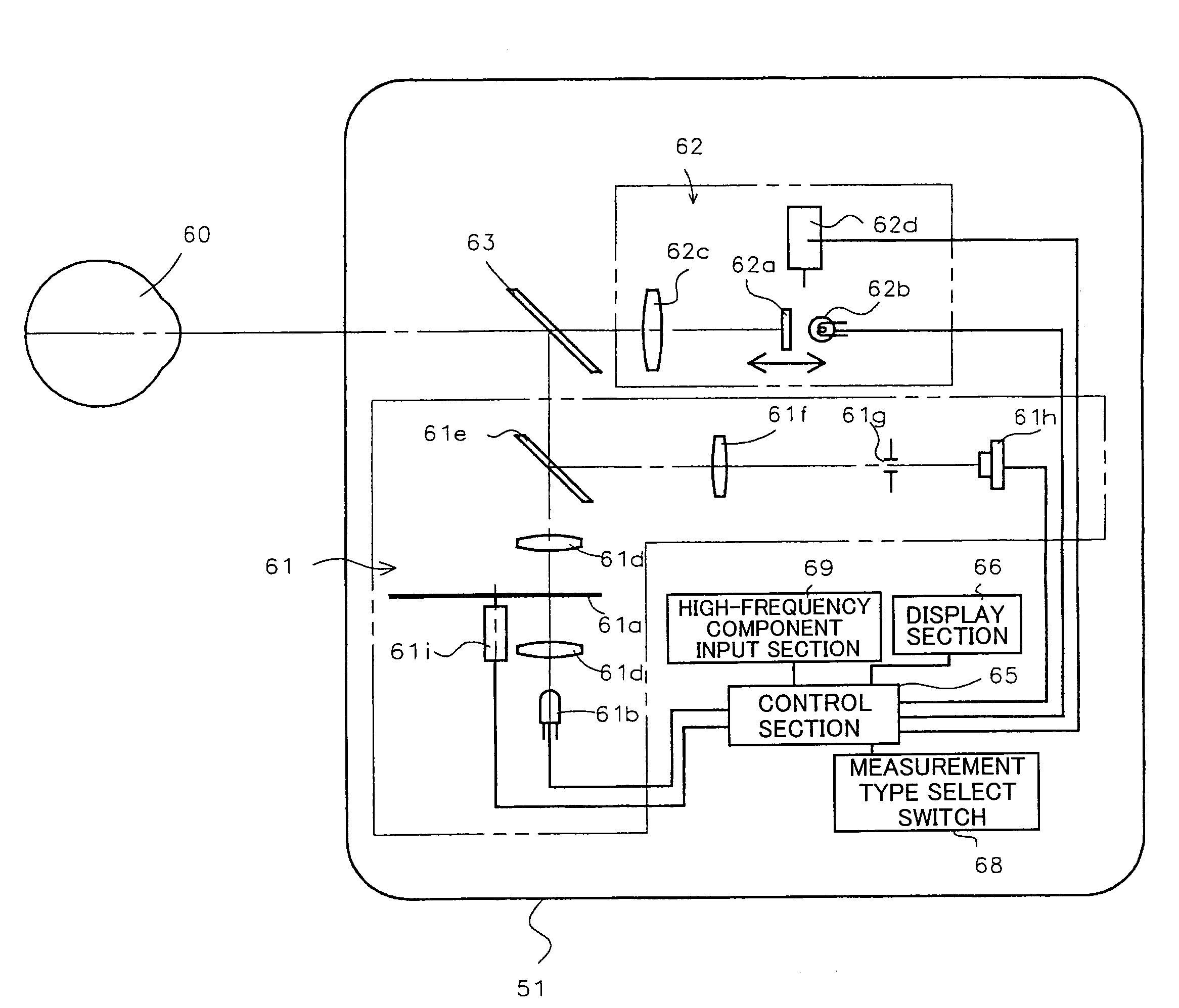
[0046]FIG. 4 is a configuration diagram of an eye refractive power measurement device 51 according to the second embodiment.

[0047]The configuration of the device used in the present invention is the same as that of the devices disclosed in the patent documents 1 and 2. The device according to the second embodiment uses retinoscopy similar to that used in the first embodiment. The basic principle for obtaining one refraction measurement is similar to that disclosed in the patent documents 1 and 2. Therefore, the details of the measurement principle are omitted. As shown in FIG. 4, the eye refractive power measurement device 51 includes a refraction measurement section 61, a projection section 62, a dichroic mirror 63, a control section 65, a display section 66, a measurement type select section 68, a high-frequency component input section 69, and the like. The projection section ...


PUM


Abstract

The present invention provides a compound device having an eye refractive power measurement function and an eye accommodation function state measurement function, preventing an increase in size and cost in comparison with a known eye refractive power measurement device, and convenient for the operator even when the measurement type is changed. An eye refractive power measurement device includes a measurement type select switch (30) which selects one of at least two types of measurements including normal refractive power measurement, which measures the refractive power of the subject s eye including spherical power, cylinder power, and astigmatism axis, and eye accommodation function state measurement, which determines a change in the refractive power of the subject s eye for high-frequency components. A refractive power measurement section (40) is a multiple meridian direction refractive power measurement section which can measure the eye refractive power in two or more meridian directions. The multiple meridian direction refractive power measurement section measures the refractive power in at least two meridian directions when performing the normal refractive power measurement. The multiple meridian direction refractive power measurement section measures the refractive power in one predetermined meridian direction when performing the eye accommodation function state measurement.

Description

TECHNICAL FIELD[0001]The present invention relates to an eye refractive power measurement device which measures the refractive power and the accommodation function state of the subject s eye.BACKGROUND ART[0002]In the field of medical treatment such as ophthalmology, a refractive power measurement device which measures the eye refractive power has been widely used. An example of the refractive power measurement device is a refractive power measurement device using retinoscopy such as the types disclosed in patent documents 1 and 2. In the field of medical treatment including ophthalmology, measurement of the eye accommodation function state has also been demanded as a more detailed refraction state. For example, a device which objectively measures the eye accommodation function state has been proposed, such as an eye accommodation function state measurement device disclosed in patent document 3.[0003]In eye accommodation function state measurement, the eye refractive power is contin...

Claims


Application Information

Patent Timeline
Patent Type & Authority Patents(United States)
IPC IPC(8): A61B3/10A61B3/103
CPCA61B3/0091A61B3/1035A61B3/103
Inventor NAGATA, TATSUHIKOAIZAWA, EISHINISHIDA, TETSUROU
Owner RIGHT MFG
Why Eureka
Try Eureka