Intralumenal stent device for use in body lumens of various diameters

a technology of intralumenal stents and lumens, which is applied in the field of intralumenal stents, can solve the problems of reducing the radial strength of stents designed for use in larger vessels, reducing the radial strength of stents designed for use in smaller vessels, so as to achieve a smaller turn radius and less resistance to expansion

Active Publication Date: 2008-01-08
MEDTRONIC VASCULAR INC
View PDF18 Cites 43 Cited by
  • Summary
  • Abstract
  • Description
  • Claims
  • Application Information

AI Technical Summary

Benefits of technology

[0013]In one embodiment, the stent has generally undulating elements connected together. Each element has a repeating pattern of undulations formed from long, short and medium sized segments connected together by hairpin turns. The hairpin turns form peaks and valleys of the stent, by which adjacent stents may be connected. In one particular embodiment, the repeating pattern is a series that includes a long segment and a first midsized segment coupled by a first peak turn. The first midsized segment is coupled to a short segment by a first valley turn. The short segment and a second midsized segment are coupled by a second peak turn, and the second midsized segment is coupled to the next series by a second valley turn. The combination of short, midsized, and long segments provide the benefits provided by elements having different length segments combined into one stent design.
[0014]In one embodiment, adjacent elements are aligned such that shorter valleys are aligned with longer peaks. Shorter peaks and shorter valleys may have a larger turn radius that those for longer peaks and longer valleys. The larger turn radius provides less resistance to expansion than a larger radius.

Problems solved by technology

However, in each case, these designs have undulations of the same length.
This foreshortening of the longitudinal length of the stent makes it difficult to ensure that a particular undulating stent will be long enough to cover the lesion effectively when expanded.
For instance, a stent designed for use in a larger vessel would likely have insufficient radial strength at a smaller diameter.
Similarly, a stent designed for use is smaller vessels would suffer from excessive foreshortening, bunching and reduced scaffolding if used at a larger diameter.

Method used


Image

  • Intralumenal stent device for use in body lumens of various diameters
  • Intralumenal stent device for use in body lumens of various diameters
  • Intralumenal stent device for use in body lumens of various diameters

Examples


Embodiment Construction

[0028]The present invention will be described with reference to the accompanying drawings. The drawing in which an element first appears is typically indicated by the leftmost digit(s) in the corresponding reference number.

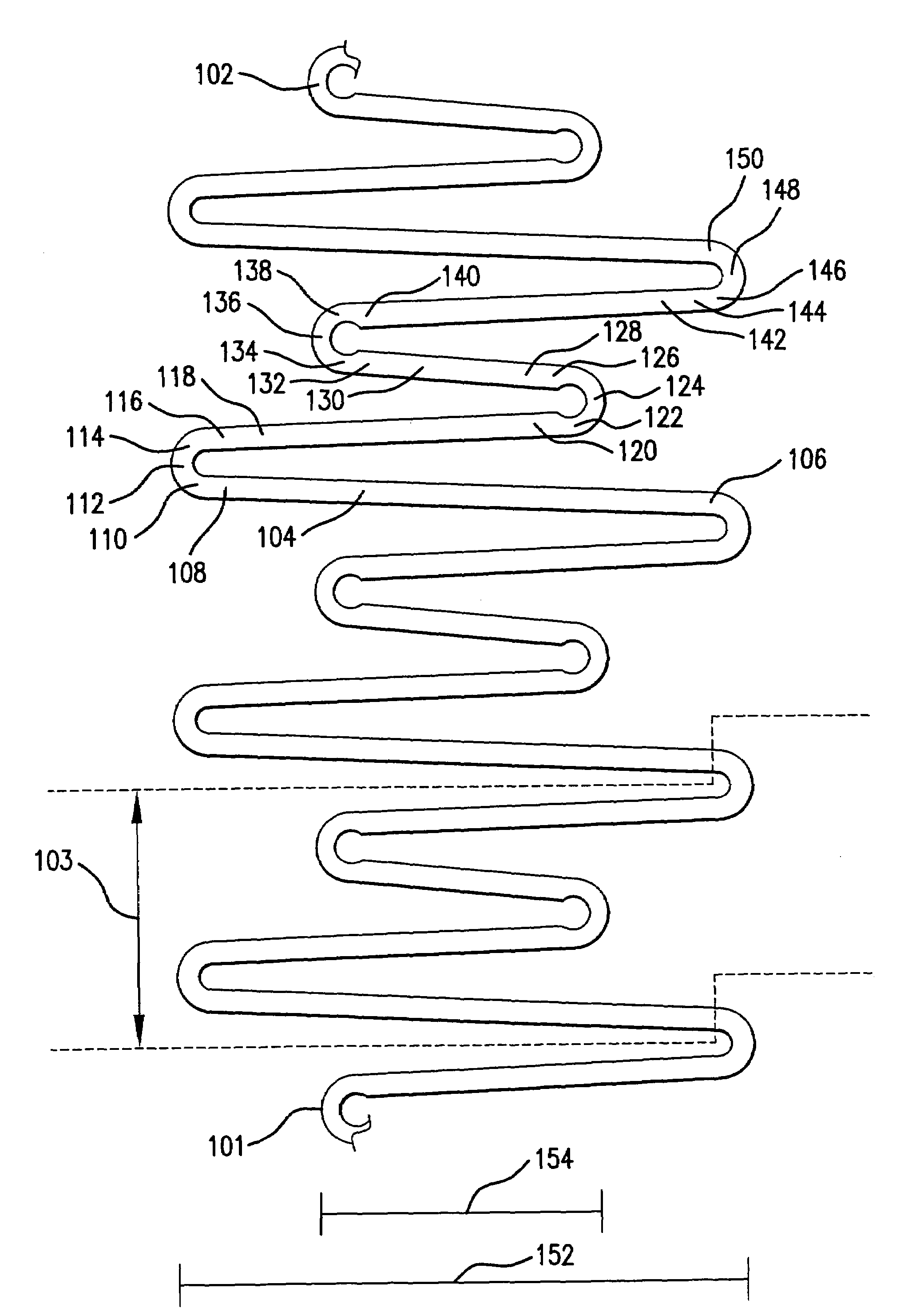
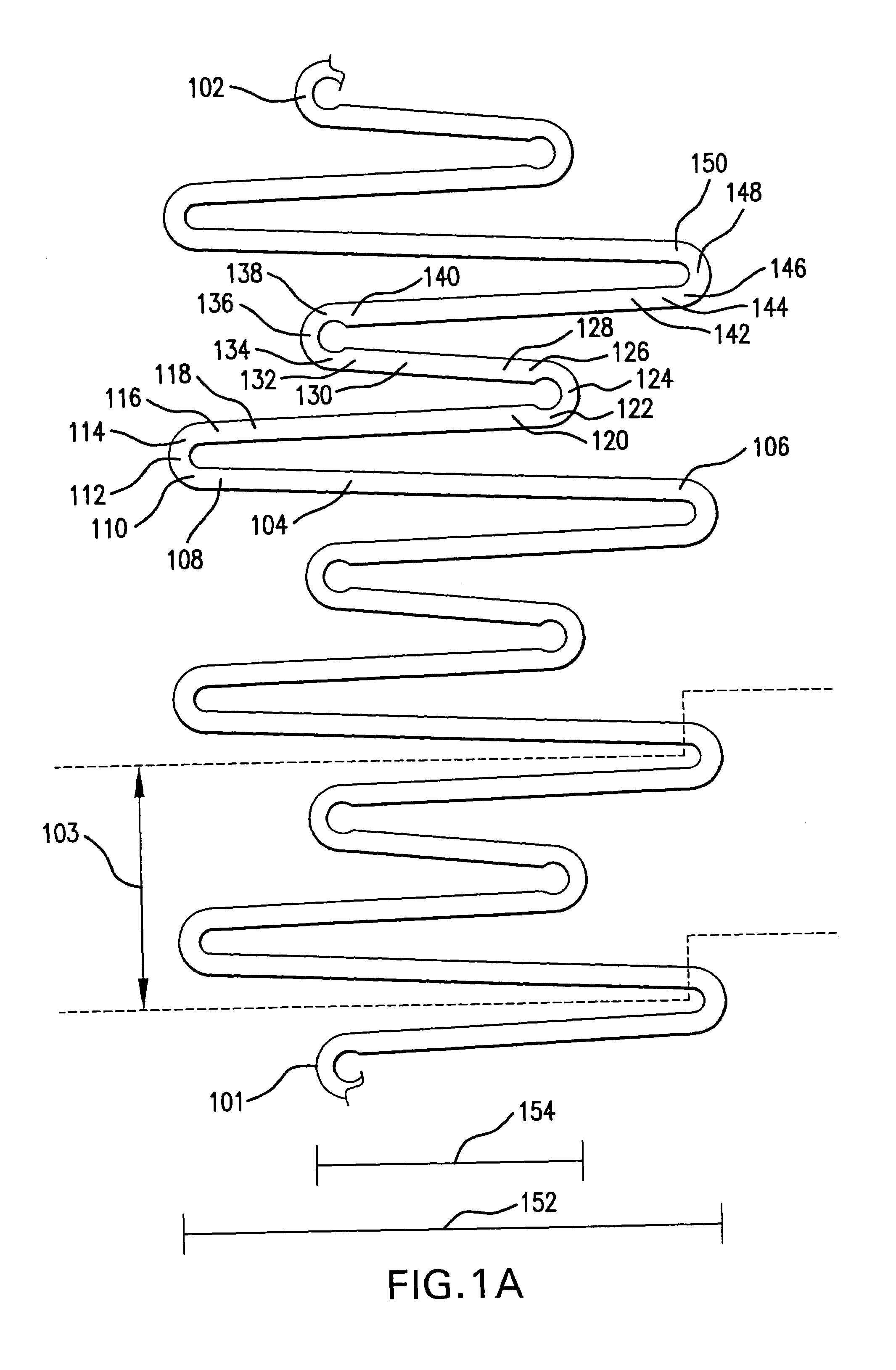
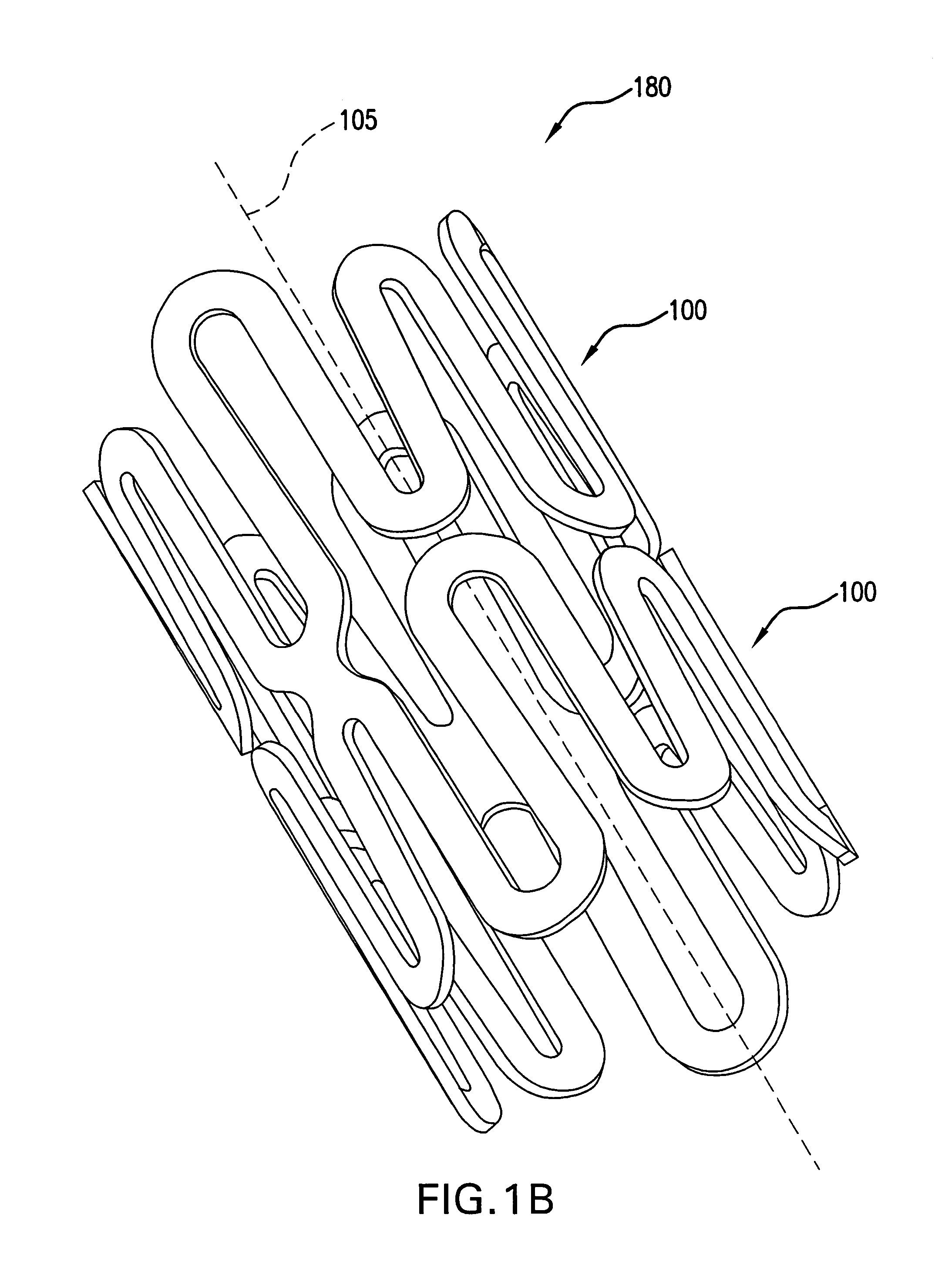
[0029]The present invention generally is directed to a stent made from generally circular single elements having a uniquely defined undulating shape. Elements are aligned on a common longitudinal axis to form a generally cylindrical body having a radial and longitudinal axis. FIG. 1a shows a single element 100 of the present invention. Element 100 is shown in a schematic, as if the generally circular element 100 has been cut between ends 101 and 102 and the element 100 has been laid out flat. FIG. 1b shows a perspective view of a stent of the present invention having two elements 100 positioned around a longitudinal axis 105, which defines a longitudinal direction.

[0030]FIG. 1b shows element 100 appearing flat, as if made from a ribbon bent into a sinusoidal shape...


PUM


Abstract

The present invention is an intralumenal stent device made up of two or more elements. Each element has undulations forming peaks and valleys and is formed from a repeating series including a long segment, a first midsized segment, a short segment, and a second midsized segment. These elements are aligned on a common axis and are connected directly to an adjacent element by a connection. The stent incorporates the advantages of having both long and short segments into a single element.

Description

FIELD OF THE INVENTION[0001]The present invention is directed to intralumenal stents for use in maintaining open collapsed lumen walls of various diameters.BACKGROUND OF THE INVENTION[0002]A wide range of medical treatments have been previously developed using “endoluminal prostheses,” which terms are herein intended to mean medical devices which are adapted for temporary or permanent implantation within a body lumen, including both naturally occurring or artificially made lumens. Examples of lumens in which endoluminal prostheses may be implanted include, without limitation: arteries, such as those located within the coronary, mesentery, peripheral, or cerebral vasculature; veins; gastrointestinal tract; biliary tract; urethra; trachea; hepatic shunts; and fallopian tubes. Various types of endoluminal prostheses have also been developed, each providing a uniquely beneficial structure to modify the mechanics of the targeted luminal wall.[0003]For example, stent prostheses have been ...

Claims


Application Information

Patent Timeline
Patent Type & Authority Patents(United States)
IPC IPC(8): A61F2/06A61F2/90
CPCA61F2/91A61F2/915A61F2002/91508A61F2002/91541A61F2230/0054A61F2002/91558A61F2220/005A61F2220/0058A61F2002/9155
Inventor ALLEN, JEFFREYDOLAN, MARKTHOMAS, RICHARD
Owner MEDTRONIC VASCULAR INC
Why Eureka
Try Eureka