Cable powder applicator

a technology of applicators and cables, applied in the field of cables, can solve the problems of contaminated machines or apparatuses in the vicinity of the applicator, affecting the operation of operators, and affecting the flow rate of powder onto the cable elements, etc., to achieve convenient passage through the mesh, facilitate the flow of powder through the mesh, and reduce the risk of operators

Inactive Publication Date: 2008-01-29
DRAKA COMTEQ BV
View PDF14 Cites 4 Cited by
  • Summary
  • Abstract
  • Description
  • Claims
  • Application Information

AI Technical Summary

Benefits of technology

[0010]To facilitate the flow of the powder through the mesh, while still maintaining a relatively regular flow rate of powder dropping onto the cable elements, the end of the stirrer located on the same side as the small opening in the hopper can preferably move relative to the mesh, in contact with the mesh and placed in such a way as to be able to scrape the mesh so as to help the powder pass through the mesh under gravity.
[0011]To allow the powder contained in the hopper to descend more easily toward the mesh, the stirrer is preferably able to rotate relative to the hopper about a rotation axis. A stirrer in the form of a vibrating blade located in the hopper could be envisioned, but the results are far inferior to those with a rotatable stirrer, as there is then a tendency to form a tunnel around the vibrating blade that results in the powder compacting laterally against the walls of the hopper, which then results in sudden detachments of blocks of powder, making the flow rate of powder onto the cable elements irregular.
[0012]To control the flow of powder in a very controlled manner along the hopper and to make it pass through the mesh easily, both for stirring the large mass of powder contained within the entire hopper and to fluidize the flow of the powder in the neck formed by the small opening in the hopper and by the mesh that closes off said opening, the stirrer preferably comprises two flat parts that can rotate about the rotation axis, which are joined together and are mutually perpendicular. A slight offset from perpendicularity could be envisioned, but if said parts of the stirrer are parallel, the torque exerted on the small part located at the small opening risks being too high, preventing fluid flow of the powder within said neck. More generally, the stirrer preferably comprises two parts joined together and angularly offset with respect to each other, said parts being placed in such a way that one part is capable of stirring the powder that is intended to be contained in the hopper and in such a way that the other part is capable of fluidizing the flow of the powder in the region of the mesh.

Problems solved by technology

One drawback of this prior art is that, since the powder is conveyed by a pressurized gas, said powder is dispersed over a wide region in the vicinity of the applicator and of the cable in the process of being assembled.
Consequently, there is a risk of other machines or apparatuses in the vicinity of the applicator being contaminated by the powder and having to be frequently stopped for cleaning, which is bothersome.
Moreover, the presence of powder on the floor within a perimeter of several meters around the applicator incurs the risk of the operators, moving around near the applicator, falling over.
Another drawback is that the flow rate of powder onto the cable elements is relatively irregular.
A minor drawback is that, during a stoppage of the applicator lasting several hours, it is necessary to ensure that the powder in the hopper of the applicator is replaced, as otherwise said powder would risk taking up moisture and forming crumbs.

Method used


Image

  • Cable powder applicator
  • Cable powder applicator
  • Cable powder applicator

Examples


Embodiment Construction

)

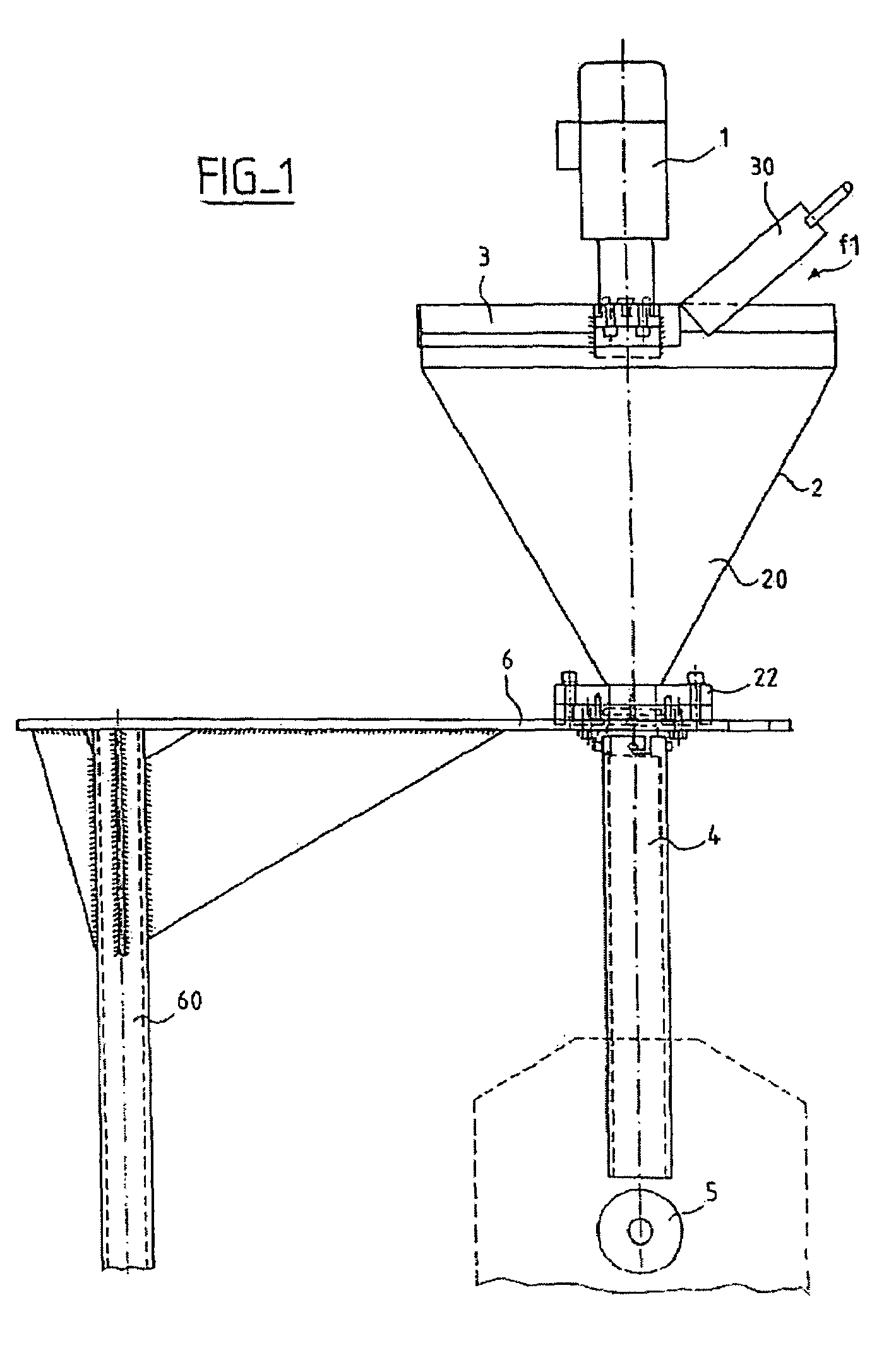
[0019]FIG. 1 shows schematically, in side view, an assembly comprising an example of an applicator according to the invention mounted on its support. The applicator according to the invention comprises a hopper 2 intended to contain a powder 20, which is introduced at the large opening of the hopper 2, said large opening being covered by a lid 3, a part 30 of which, able to swing away, makes it possible, when it is open, to introduce the powder along the direction of the arrow f1. At the small opening of the hopper 2 there is a ring 22 that is fixed to a support 6, the support being mounted on a pivoting leg 60. Fixed under the support 6 is a tube 4 intended to guide the powder after it has passed through the ring 22. Passing beneath the bottom opening of the tube 4 are the cable elements, denoted by 5, which elements may in particular be optical fibers, or tubes containing optical fibers, in particular loose tubes, which may be arranged around a central strength member, or reinfor...


PUM

PropertyMeasurementUnit
half-angleaaaaaaaaaa

Abstract

The invention relates to the field of applicators for applying moisture-absorbent powder on cable elements. This is an applicator for applying moisture-absorbent powder on cable elements which comprises a hopper intended to contain the powder, a mesh closing the small opening of the hopper and a mechanical powder stirrer located inside the hopper, the stirrer being placed in the hopper in such a way as to be able to make the powder flow through the mesh under gravity, the applicator having no means for conveying the powder that has passed through the mesh, which powder continues to flow under gravity as far as the cable elements. The type of cable in question is in particular a fiber-optic cable.

Description

CROSS-REFERENCE TO RELATED APPLICATIONS[0001]This application is based on French Patent Application No. 03 07 884 filed Jun. 30, 2003, the disclosure of which is hereby incorporated by reference thereto in its entirety, and the priority of which is hereby claimed under 35 U.S.C. § 119.BACKGROUND OF THE INVENTION[0002]1. Field of the Invention[0003]The invention relates to the field of applicators for applying moisture-absorbent powder on cable elements and to the field of methods of applying moisture-absorbent powder on cable elements. This powder has the function, once the cable has been produced, of absorbing moisture lying in certain elements of the cable so as to prevent this moisture from degrading the properties of these cable elements and of preventing this moisture from propagating along these cable elements.[0004]2. Description of the Prior Art[0005]According to one prior art, it is known to make cable elements, such as optical fibers, or tubes containing optical fibers, pa...

Claims


Application Information

Patent Timeline
Patent Type & Authority Patents(United States)
IPC IPC(8): B05C19/00B05C11/00B05C19/04G02B6/44H01B13/32
CPCB05C19/04G02B6/4483G02B6/4494H01B13/321G02B6/44384
Inventor FLEURY, DANIEL
Owner DRAKA COMTEQ BV
Why Eureka
Try Eureka