Vending machine tracking system

a vending machine and tracking system technology, applied in the field of vending machines, can solve the problems of limiting the ability of operators to expand their business, affecting the operation of vending machines, and being highly vulnerable to the theft of coins by their service personnel

a vending machine and tracking system technology, applied in the field of vending machines, can solve the problems of limiting the ability of operators to expand their business, affecting the operation of vending machines, and being highly vulnerable to the theft of coins by their service personnel

US7357239B2Inactive Publication Date: 2008-04-15BEAVER MACHINE

Image

  • Vending machine tracking system
  • Vending machine tracking system
  • Vending machine tracking system

Examples


Embodiment Construction

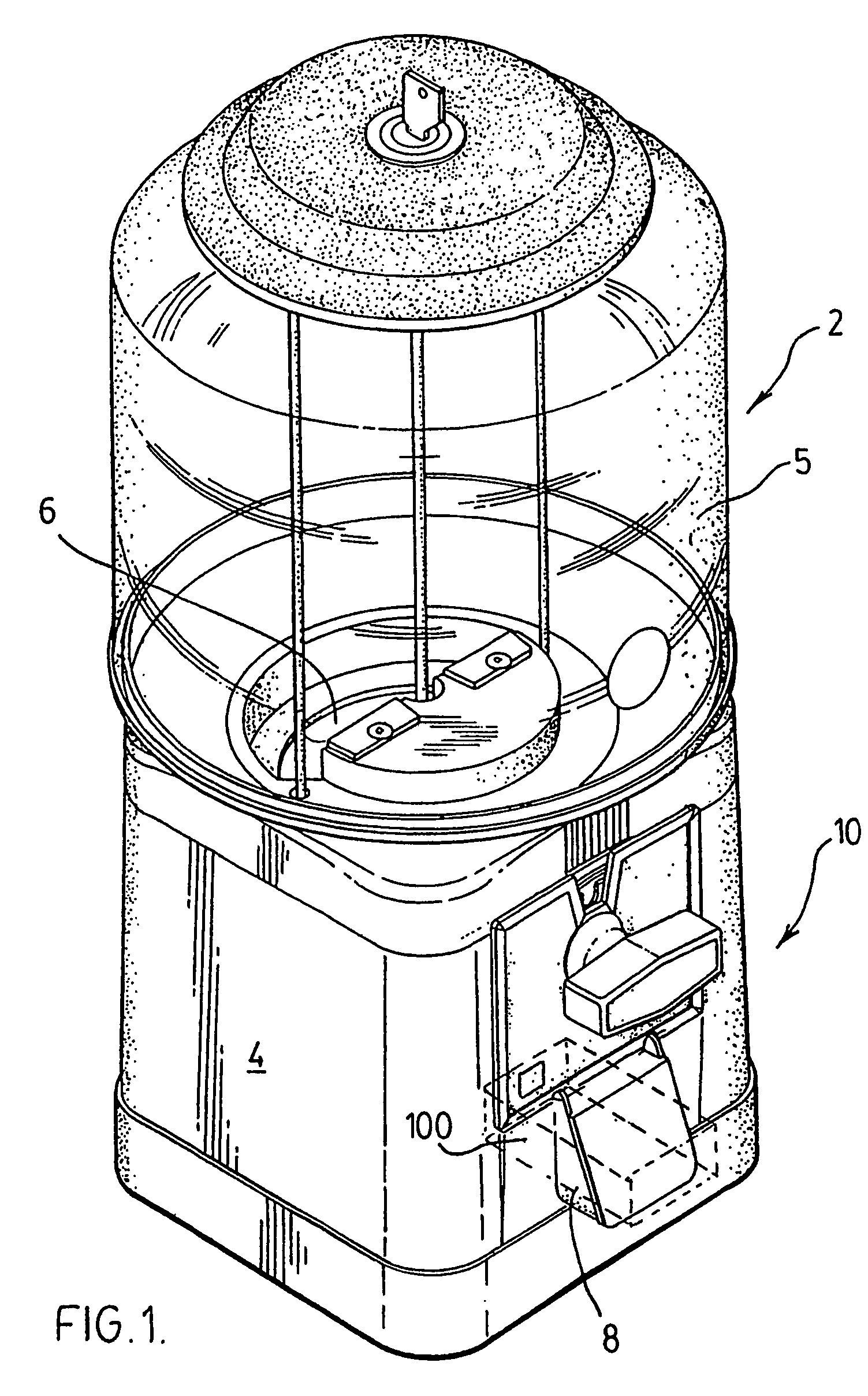
[0029]FIG. 1 illustrates a typical bulk vender 2 in which the system of the invention may be employed. The vender 2 conventionally includes a lower housing 4 enclosing the workings of the coin mechanism 10 and a cash box (not shown) for collecting deposited coins or tokens 1, a transparent article storage bin 5 for storing merchandise such as gum balls or other articles to be dispensed, and a turntable 6 which is rotated by rotation of the coin mechanism 10 to align one of a plurality of product conveyors with the opening to a dispensing chute 8, as is well known. A vender of this type is described and illustrated in U.S. Pat. No. 5,954,181 for a “Coin Mechanism with Magnetic Locking System” issued on Sep. 21, 1999, which is incorporated herein by reference. It will be appreciated that this is merely one example of a bulk vender in which the invention can be implemented, and the description thereof is not intended to be limiting.

[0030]Although the invention will be described with re...


PUM


Abstract

A tracking system counts events in the operation of multiple machines or devices over a wide geographic area. For example, for bulk venders the system counts each vend responsive to rotation through a cycle of the coin mechanism, and preferably records the date and time of each vend. An active tag has a memory for storing data representing a vending event, for example the date and time of the event. The data is periodically read by an interrogator, which downloads the data stored in the tag memory and erases the memory to reset the tag for continued monitoring of the vender. With this information an operator can reconcile revenues, track when sales take place and over what period of time, and track the work habits of service personnel.

Description

FIELD OF INVENTION[0001]This invention relates to vending machines. In particular, this invention relates to a system for tracking vending machines and vended merchandise.BACKGROUND OF THE INVENTION[0002]Bulk venders, colloquially known as “gum ball machines”, are widely used for dispensing confectioneries and other small articles of merchandise. A typical bulk vender has a hopper assembly comprising a transparent globe which functions as a merchandise storage bin, seated over a dispensing wheel which revolves in a hopper. A patron deposits the required coinage into the coin mechanism and turns the handle, which rotates the dispensing wheel to convey a preset amount of merchandise to the dispensing chute. The hopper assembly is located over a body which is mounted on a base, defining a secure compartment containing a cash box into which the coin mechanism ejects the deposited coins.[0003]Bulk venders are typically purchased and maintained by vender operators, who install and service...

Claims


Application Information

Patent Timeline
15 Apr 2008
Publication
US7357239B2
IPC
G07F5/02; G07F5/00; G07F5/10; G07F5/18; G07F5/22; G07F9/02
CPC
G07F5/22; G07F9/026; G07F11/002; G07F9/001; G07F9/002; Y10S200/03
Inventors
SCHWARZLI, JOSEF W; SCHWARZLI, BERNARD R.