Tubular, especially can-shaped, receptacle for the accommodation of fluids, a method of manufacture, and use

a technology for receptacles and fluids, which is applied in the field of can-shaped receptacles for the accommodation of fluids, can solve the problems of limited use or inability to accommodate fluids in tubes, tubes with no base that can serve as a standing surface, and can only be used for limited periods or not suitable at all to accommodate fluids, etc., to achieve the effect of increasing the compressive strength of the receptacle, increasing the pressure-bearing capacity and excess pressure-

Active Publication Date: 2008-04-29
HUHTAMAKI RONSBERG ZWEIGNIEDERLASSUNG DER HUHTAMAKI DEUT
View PDF22 Cites 26 Cited by
  • Summary
  • Abstract
  • Description
  • Claims
  • Application Information

AI Technical Summary

Benefits of technology

[0009]One aspect of the invention lies in the fact that the top section is constructed in the shape of a shoulder. This makes it possible, on the one hand, to lay the top section flat against the circumferential tubular body and to seal it to it. On the other hand, the shoulder-shaped construction may create a junction with a closure device, which has an increased pressure-bearing capacity vis-a-vis the prior art. The shoulder-shaped construction of the top section also provides, compared with a level top section, a greater contact area both with the tubular body and for attaching a closure device. As a result, there is a greater sealing surface available between the shoulder-shaped top section and the tubular body, as well as between the shoulder-shaped top section and the closure device, thereby achieving an increase in stability and thus in the compressive strength of the receptacle.
[0010]The closure device is preferably constructed to be resealable, making it possible to remove only part-quantities of the volume from the tubular receptacle and to then close this again after removal. The closure device is preferably constructed in such a way that any excess pressure that is present can be reduced in a slow and controlled manner, say by means of a screw-type closure.
[0011]In one embodiment of the invention, the shoulder-shaped top section is at least partially enclosed, especially in the shape of a shoulder, by an upper edge of the tubular body and sealed with this. This embodiment has the decisive advantage that any excess pressure present or developing in the tubular receptacle helps to stabilize seal seams in a shoulder area. The excess pressure works on this occasion on the inner surface of the shoulder-shaped top section, pressing the top section against the edge of the tubular body enclosing the shoulder-shaped top section. The tubular body is preferably made of a flexible material. This, however, has an intrinsic firmness, possibly including a fabric or metallic or similar interlining, with the result that a shoulder of the top section may be pressed against a shoulder of the tubular body. A seal located in this area between the top section and the tubular body is consequently further reinforced by the added exertion of an inner pressure in the tubular receptacle, which in turn creates an additional sealing effect.
[0024]The circular base section is preferably dimensionally stable, though it may also be constructed to be flexible. A dimensionally stable construction here guarantees, in an advantageous manner, a stable standing surface for the tubular receptacle. The advantage of a flexible construction to the circular base section, in contrast, consists in an improved ability to be folded up and disposed of when the receptacle is empty and has to be discarded.

Problems solved by technology

All these tubular receptacles described in the publications have certain disadvantages, especially with regard to their use.
Use is therefore restricted and only possible for select products.
Thus bag-type packaging, and tubes especially, have only limited use or are not suitable at all to accommodate fluids.
In addition, tubes have no base that can serve as a standing surface.
Another essential disadvantage, which all the aforementioned tubular receptacles have in common, consists in the fact that the said receptacles are not suitable for accommodating, and especially storing and transporting, nor for deliberately dispensing, drinks, especially carbonated drinks.
However, they are both expensive to manufacture and disadvantageous in terms of their weight and disposal.

Method used


Image

  • Tubular, especially can-shaped, receptacle for the accommodation of fluids, a method of manufacture, and use
  • Tubular, especially can-shaped, receptacle for the accommodation of fluids, a method of manufacture, and use

Examples


Embodiment Construction

[0032]In the following description the same reference numerals are used for the same and similarly acting parts.

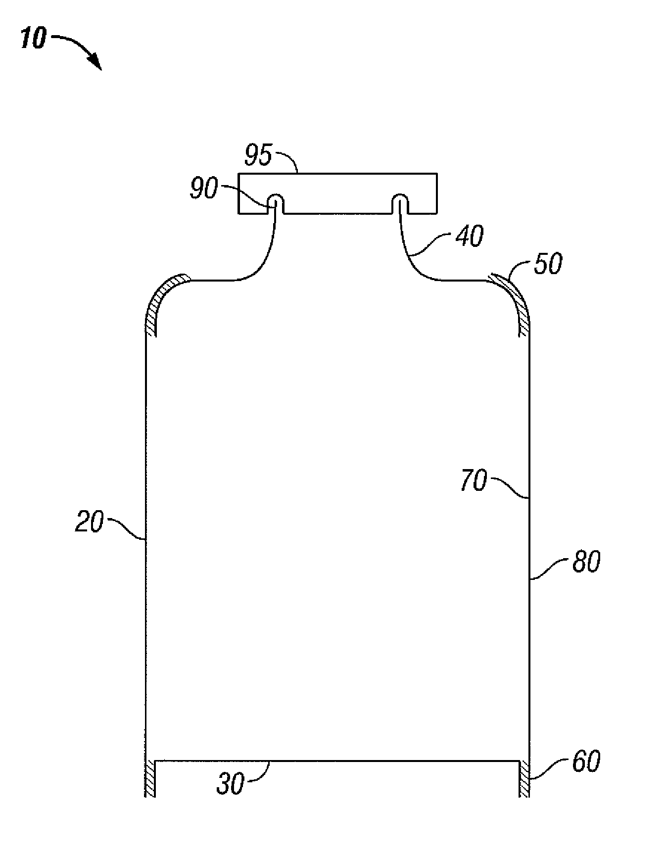
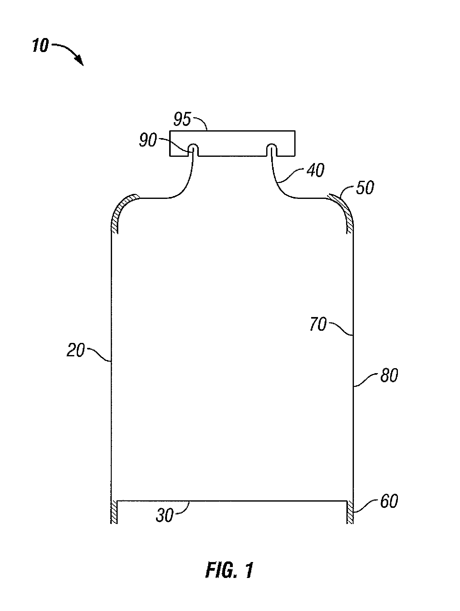
[0033]FIG. 1 depicts a tubular receptacle 10. The tubular receptacle has a tubular body 20 and a base section 30 and a shoulder-shaped top section 40. The base 30 is inserted in the tubular body 20 from below and is sealed along a lower edge 60 with the tubular body 20. In the head of the tubular body 20 the shoulder-shaped top section 40 with a collar-shaped part 90 is located. The shoulder-shaped top section 40 is sealed with an upper edge 50 of the tubular body 20. The upper edge 50 encloses the shoulder-shaped top section 40 in the shape of a shoulder. The tubular body 20 is manufactured from a laminate, which has a barrier coating (not depicted). The layer 70 of the laminate facing the inside of the receptacle consists of polyethylene. The layer 80 of the laminate facing the outside of the receptacle also consists of this material. The same layer structure applies to ...


PUM

PropertyMeasurementUnit
circumferenceaaaaaaaaaa
thicknessaaaaaaaaaa
widthaaaaaaaaaa

Abstract

Tubular, especially can-shaped, receptacle for the accommodation of fluids, especially drinks, with a tubular body and a base and top section attached to this, wherein the top section is constructed in the shape of a shoulder and is suitable for attaching a closure device, especially a resealable one. The shoulder-shaped top section is at least partially enclosed, especially in the shape of a shoulder, by an upper edge of the tubular body and sealed with this.

Description

BACKGROUND OF THE INVENTION[0001]1. Field of the Invention[0002]The invention concerns a tubular, especially can-shaped, receptacle for the accommodation of fluids, a method of manufacture, and a use of the receptacle.[0003]2. Description of the Related Art[0004]A large number of tubular receptacles are known from the prior art. These normally serve to accommodate pastes, creams, gels and fluids. The tubular receptacles are usually tube-shaped, though in recent times they are also can-shaped. DE 32 08 625 A1 and DE 44 29 148 A1 describe processes for manufacturing and filling such tubes. JP 2001 080 650 A describes a pouch-shaped receptacle with a base. A can-shaped tubular receptacle is described, for instance, in WO 99 / 64227. A series of other can-shaped tubular receptacles can be found in the publications EP 0 595 587 B1, EP 0 833 774 B1, WO 00 / 00396 and F1 109 193 B.[0005]All these tubular receptacles described in the publications have certain disadvantages, especially with rega...

Claims


Application Information

Patent Timeline
Patent Type & Authority Patents(United States)
IPC IPC(8): B65D1/40B65D3/22B65D8/04B65B1/04B65D23/02
CPCB65D11/04B65D23/02Y10T29/49982Y10T29/49826Y10T29/49986
Inventor MICHALSKY, ANDREAS
Owner HUHTAMAKI RONSBERG ZWEIGNIEDERLASSUNG DER HUHTAMAKI DEUT
Why Eureka
Try Eureka