AI technical title is built by Patsnap AI team. It summarizes the technical point description of the patent document.
a strain relief member and plug connector technology, applied in the direction of coupling device details, coupling device connection, printed circuit, etc., can solve the problem that the conventional simple structure strain relief member is not suitable for us
Inactive Publication Date: 2008-04-29
HON HAI PRECISION IND CO LTD
View PDF5 Cites 34 Cited by
Summary
Abstract
Description
Claims
Application Information
AI Technical Summary
This helps you quickly interpret patents by identifying the three key elements:
Problems solved by technology
Method used
Benefits of technology
Benefits of technology
[0007]Accordingly, an object of the present invention is to provide a plug connector with an improved strain relief member to provide enough strain relief to cables thereof.
Problems solved by technology
When formed in 1990, the original goals were limited to define de facto mechanical envelopes within disk drives can be developed to fit compact computer and other small products.
Thus, the conventional simple-structure strain relief member is not suitable to use in such case.
Method used
Image
Click on the blue label to locate the original text in one second.
Reading with bidirectional positioning of images and text.
Examples
Embodiment Construction
[0015]Reference will now be made to the drawing figures to describe the present invention in detail.
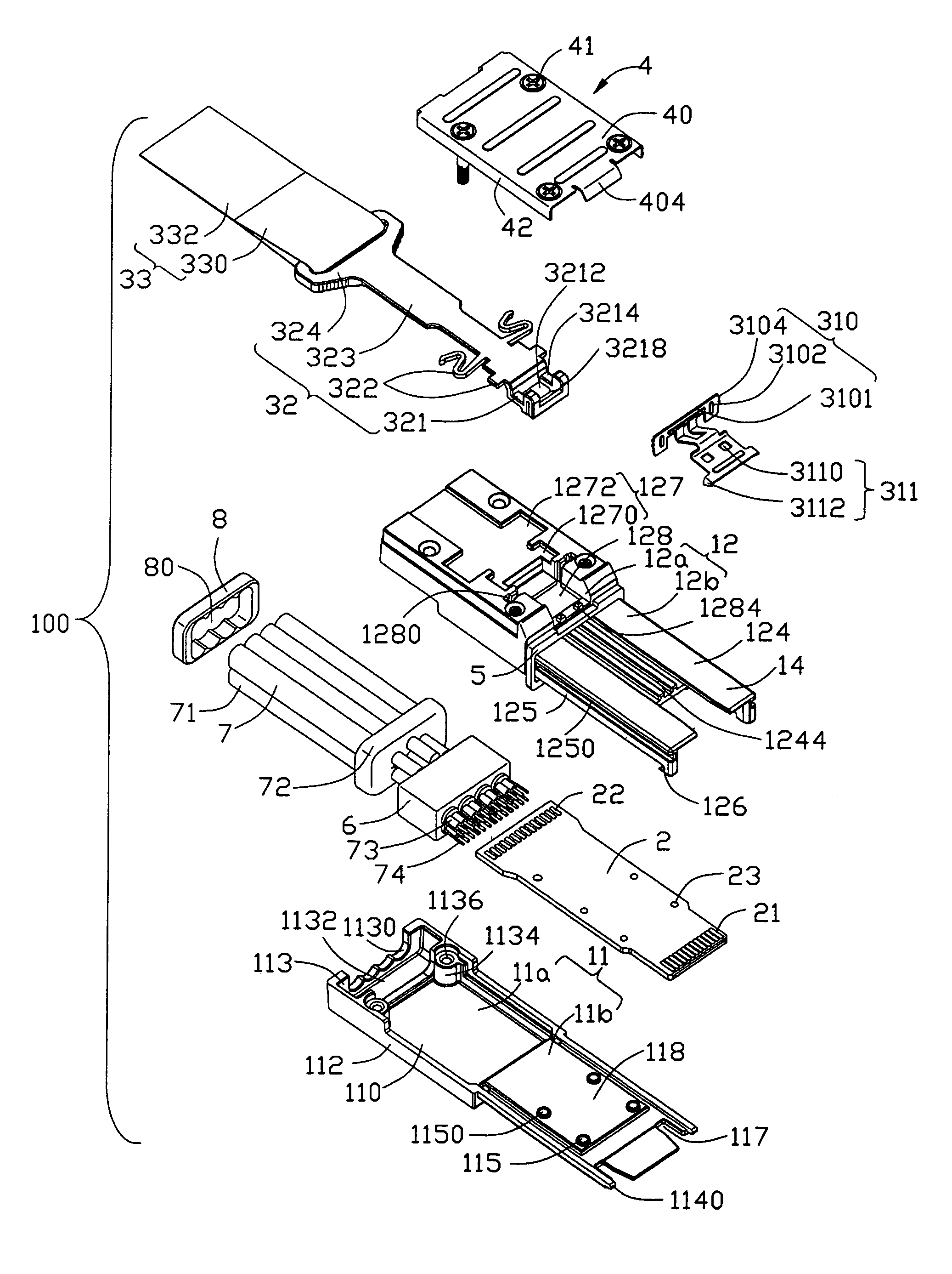
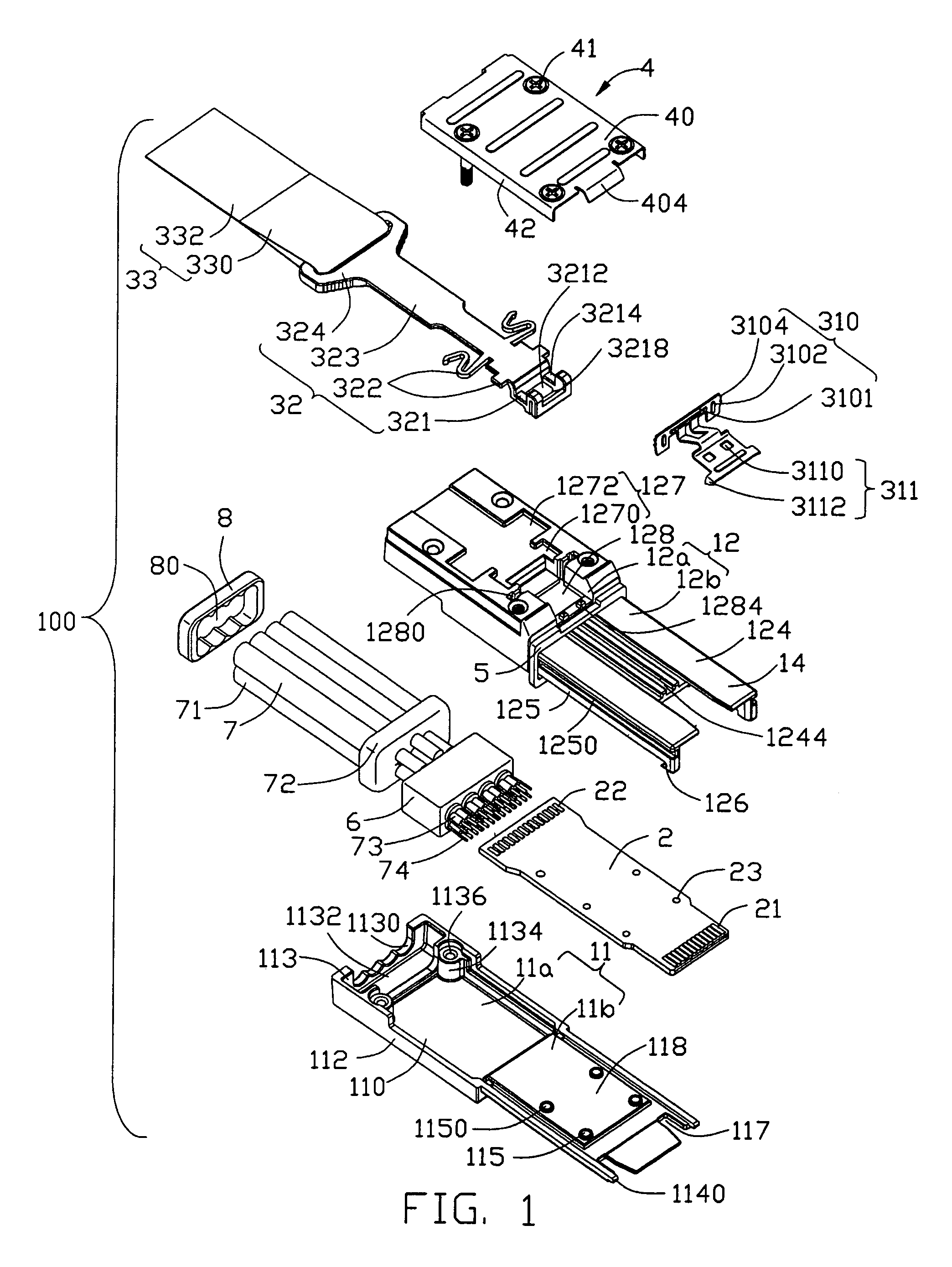
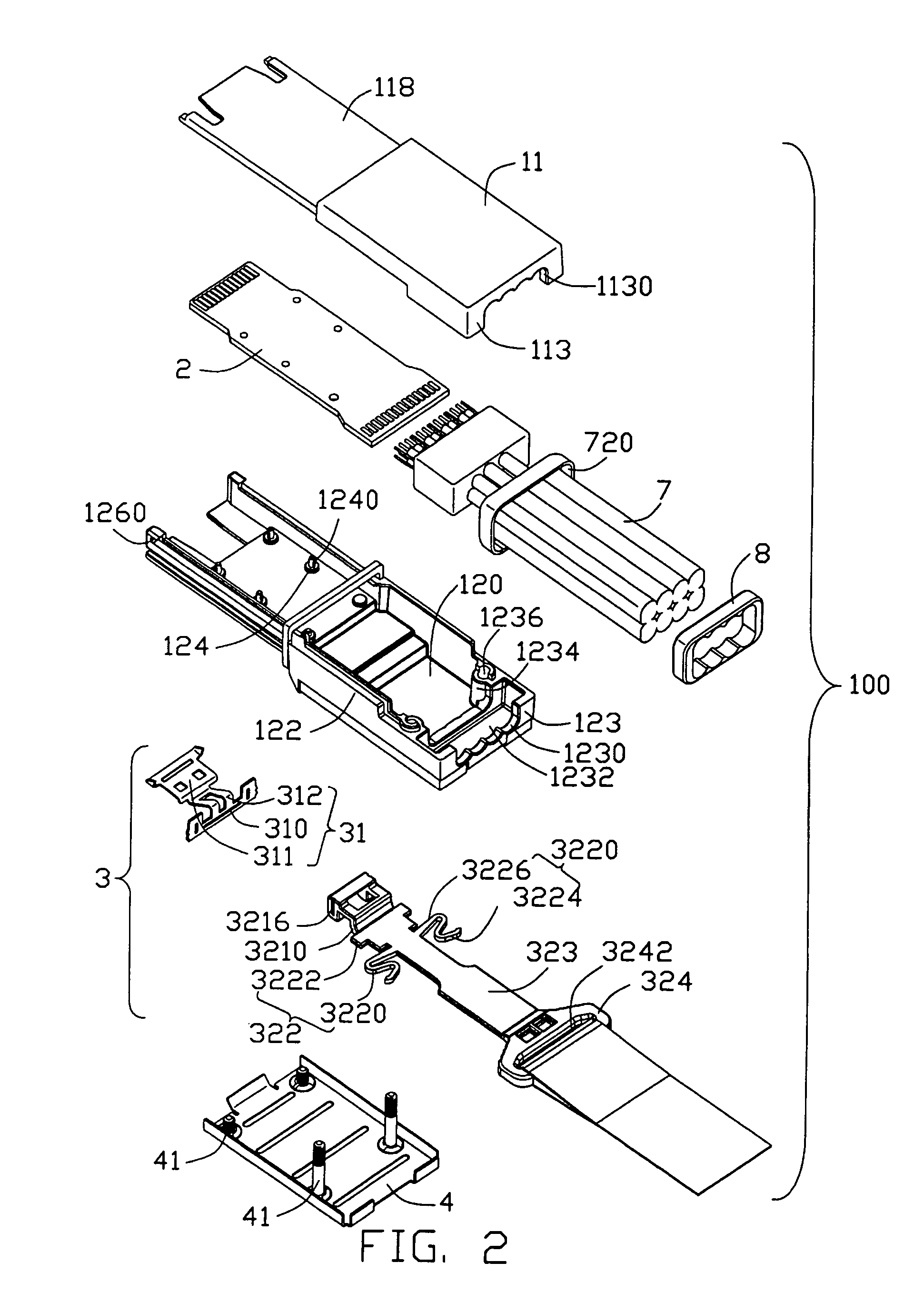
[0016]Referring to FIGS. 1-3, a plug connector 100 in accordance with the present invention comprises a housing 1, a circuit card 2 located in the housing 1, a cable set 7 comprising a plurality of cables 71 respectively electrically connecting with the circuit card 2, a latch mechanism 3 assembled to the housing 1, a metal shell 4 assembled to the housing 1 to partially cover the latch mechanism 3, and a strain relief member 8 electrically connecting with the cables 71.
[0017]Please refer to FIGS. 1-2, the housing 1 of the present invention is made of metal material and comprises a base 11, a cover 12 engagble with the base 11 and a receiving space 15 (FIG. 5) formed between the base and the cover 11, 12. The metal housing 1 also comprises a rectangular base portion 13 and an elongated tongue portion 14 extending forwardly from the base portion 13.
[0018]The base 11 comprises a first b...
PUM
Abstract
A plug connector (100) includes a housing (1), a PCB (2) received in the housing, a cable set (7) electrically connecting with the PCB, a pulling member (32) moveable relative to the housing in a horizontal direction, a latch member (31) discrete from the pulling member and assembled to the housing for latch with a complementary connector, and a pull tape (33) discrete from the pulling member and assembled to the pulling member. The cable set includes a plurality of conductors (73, 74) connecting with the PCB, a metal braiding layer (72) forming a space and an outer jacket surrounding the metal braiding layer. A strain relief member (8) is assembled to the cable set and surrounded by the metal braiding layer.
Description
CROSS-REFERENCE TO RELATED APPLICATIONS[0001]The present invention is a CIP (continuation-in-part) of U.S. patent application Ser. No. 11 / 201,521 filed on Aug. 11, 2005 now U.S. Pat. No. 7,114,980. Furthermore, t his application is related to U.S. patent application Ser. No. 11 / 201,521 filed on Aug. 11, 2005 and entitled “CABLE CONNECTOR ASSEMBLY WITH LATCHING MECHANISM”, U.S. patent application Ser. No. 11 / 201,461 filed on Aug. 11, 2005 and entitled “CABLE CONNECTOR ASSEMBLY WITH LATCHING MECHANISM”, U.S. patent application Ser. No. 11 / 268,906 filed on Nov. 8, 2005 and entitled “CABLE CONNECTOR ASSEMBLY WITH LATCHING MECHANISM”, U.S. patent application Ser. No. 11 / 268,902 filed on Nov. 8, 2005 and entitled “JUXTAPOSED CABLE CONNECTOR ASSEMBLIES”, and U.S. patent application Ser. No. 11 / 322,692 filed on Dec. 30, 2005 and entitled “STACKED CONNECTOR ASSEMBLY”, U.S. patent application Ser. No. 11 / 213,048 filed on Aug. 26, 2005 and entitled “CABLE CONNECTOR ASSEMBLY WITH EMI GASKET”, a...
Claims
Application Information
Patent Timeline
Application Date:The date an application was filed.
Publication Date:The date a patent or application was officially published.
First Publication Date:The earliest publication date of a patent with the same application number.
Issue Date:Publication date of the patent grant document.
PCT Entry Date:The Entry date of PCT National Phase.
Estimated Expiry Date:The statutory expiry date of a patent right according to the Patent Law, and it is the longest term of protection that the patent right can achieve without the termination of the patent right due to other reasons(Term extension factor has been taken into account ).
Invalid Date:Actual expiry date is based on effective date or publication date of legal transaction data of invalid patent.

