Mechanical splice connector with sequential splice and strain relief

a mechanical splice connector and fiber optic technology, applied in the direction of optics, instruments, optical light guides, etc., can solve the problems of not always desirable to simultaneously terminate and strain relieve a field optical fiber, damage the field optical fiber or the connector, and the splice cannot be reversed and reworked, etc., to achieve the effect of adequate strain reli

Inactive Publication Date: 2010-02-09
CORNING OPTICAL COMM LLC
View PDF24 Cites 12 Cited by
  • Summary
  • Abstract
  • Description
  • Claims
  • Application Information

AI Technical Summary

Benefits of technology

[0008]In one aspect, the present invention is directed to a fiber optic mechanical splice connector configured to sequentially perform splice actuation, followed by strain relief actuation. The connector first aligns and retains the bare glass portions of at least one stub optical fiber and at least one adjoining field optical fiber in optical communication. The connector then strain relieves the coated portion of the field optical fiber having a diameter up to and including about 250 microns, or alternatively, strain relieves the buffered portion of the field optical fiber having a diameter greater than about 250 microns up to about 900 microns or more. In one preferred embodiment, the connector includes a single, multiple-position reversible actuator that is movable from an unactuated position to a first actuated position to splice the stub optical fiber and the field optical fiber together (splice actuation position), and is further movable from the first actuated position to a second actuated position to strain relieve the field optical fiber to the connector (strain relief actuation position). The actuator preferably comprises a cam member having an internal geometry that engages and exerts a radial compressive force to at least one of a pair of splice components, thereby biasing the splice components together with the bare glass portions of the stub optical fiber and the field optical fiber aligned and retained therebetween. The same cam member subsequently strain relieves the field optical fiber by applying a biasing force to one or more flexible, and in some embodiments sacrificial, strain relief elements capable of accommodating various diameters of the field optical fiber. The strain relief elements are shaped such that adequate strain relief is provided on a coated portion of a field optical fiber without over-crimping a buffered portion of a field optical fiber. In particular, the cam member is preferably flexible enough to accommodate field optical fibers of various diameters, while providing adequate strain relief on the coated portion of a field optical fiber having a diameter up to and including about 250 microns without over-crimping the buffered portion of a field optical fiber having a diameter greater than about 250 microns and up to about 900 microns or more. In other embodiments, an inner portion of the cam member is adapted to “break away” to accommodate larger diameter field optical fibers.
[0010]In yet another aspect, the present invention is directed to a mechanical splice connector including a first actuator for splice actuation, and a second actuator for strain relief actuation. For example, a mechanical splice connector is provided including separate cam members that are actuated sequentially to first perform splice actuation and then subsequently perform strain relief actuation. The first cam member is actuated, and preferably, is rotated from an unactuated position to a first actuated position for completing the optical splice between the stub optical fiber and the field optical fiber (splice actuation position). As the first cam member is rotated, the cam surface defined by the internal geometry of the cam member engages at least one splice component, thereby exerting a radial compressive biasing force on the splice component to align and retain the bare glass portions of the optical fibers therebetween. After the splice actuation position is reached, the optical continuity of the splice coupling may be determined using a VFL, such as the Corning Cable Systems CTS or any other known continuity test system. Once acceptable optical continuity has been determined, the second cam member is then rotated from its unactuated position to a second actuated position for strain relieving the field optical fiber to the connector (strain relief actuation position). The coated portion, or alternatively the buffered portion, of the field optical fiber is strain relieved as the cam surface defined by the internal geometry of the second cam member applies a biasing force to one or more strain relief elements positioned on the connector rearward of the splice components. For example, a strain relief element may include crimp fingers of a strain relief body that flex, deform or collapse inwardly about the coated portion or alternatively the buffered portion of the field optical fiber. The crimp fingers are preferably flexible and / or collapsible to allow strain relief on the smaller diameter of a coated field optical fiber without over-crimping the larger diameter of a buffered field optical fiber. Following splice actuation and prior to strain relief actuation, the first cam member is reversible without potentially damaging the field optical fiber or the connector. Following splice actuation and strain relief actuation, the second cam member and the strain relief element(s) restrain the field optical fiber from torsion and localized bending during final assembly of the connector. In another embodiment, the first cam member may be mechanically coupled to the second cam member, for example, by a linkage, gear arrangement, rack and pinion, etc., such that movement of the first cam member drives the subsequent movement of the second cam member.

Problems solved by technology

A drawback to the conventional strain relief technique for mechanical splice connectors is that once the field optical fiber is strain relieved, the splice cannot be reversed and reworked without destroying the connector assembly and potentially damaging the field optical fiber or the connector.
Although seemingly advantageous, it is not always desirable to simultaneously terminate and strain relieve a field optical fiber to a mechanical splice connector.
Further, if the optical splice is unacceptable, additional time and labor must be expended to first reverse the strain relief before removing or repositioning the field optical fiber and again terminating and strain relieving the field optical fiber to the connector.

Method used


Image

  • Mechanical splice connector with sequential splice and strain relief
  • Mechanical splice connector with sequential splice and strain relief
  • Mechanical splice connector with sequential splice and strain relief

Examples


Embodiment Construction

[0026]Reference will now be made in detail to the present preferred embodiments of the invention, examples of which are illustrated in the accompanying drawings. Whenever possible, the same reference numerals are used throughout the drawings to refer to the same or like parts. Although apparatus and methods for sequential splice actuation and strain relief actuation are described and shown in the accompanying drawings with regard to a specific type of fiber optic mechanical splice connector, it is envisioned that the functionality of the various apparatus and methods may be applied to any now known or hereafter devised fiber optic connector in which it is desired to optically align one or more mating optical fibers and to strain relieve at least one of the mating optical fibers.

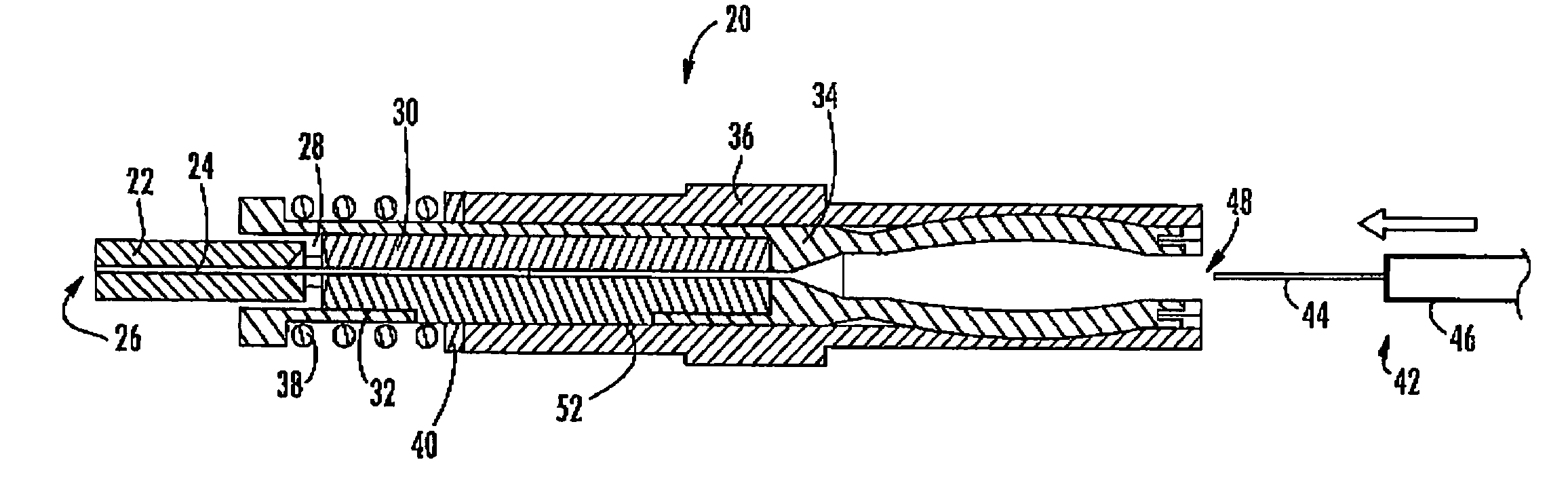
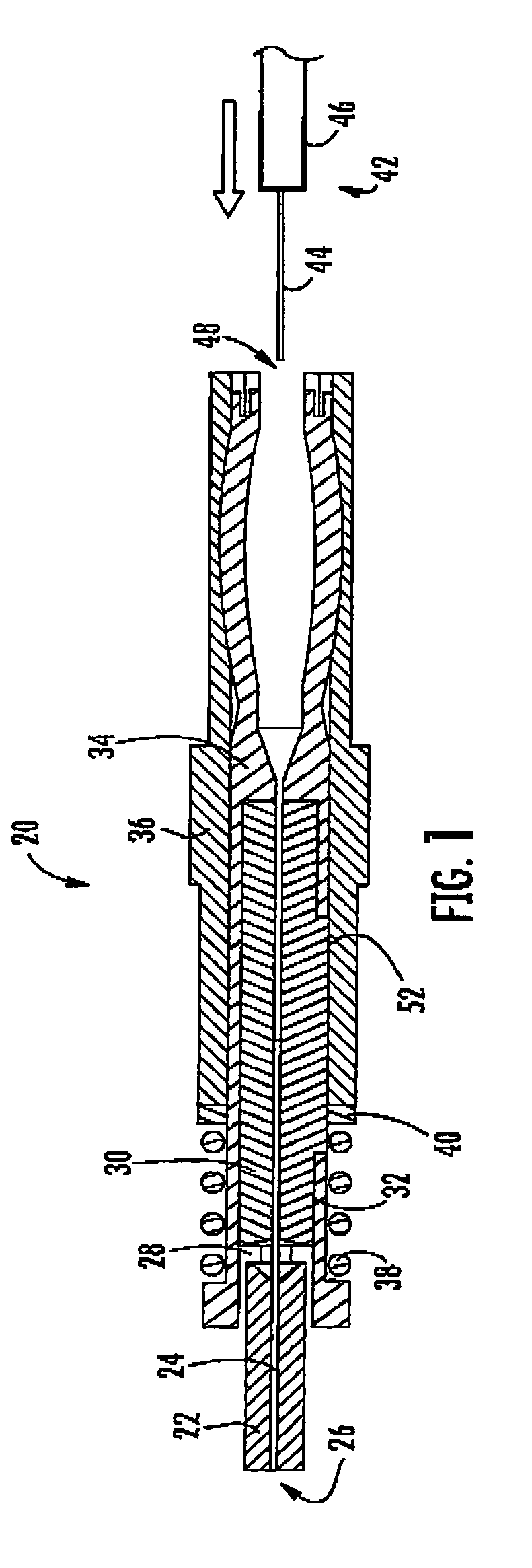
[0027]Referring now to FIG. 1, a lengthwise cross-sectional view of an exemplary fiber optic mechanical splice connector 20 is shown. The connector 20 includes a connector ferrule 22 defining a lengthwise-ext...


PUM


Abstract

A mechanical splice connector is shown and described for sequentially performing a splice actuation followed by a strain relief actuation by rotating a single, multiple-position cam member or multiple cam members from an unactuated position to a first actuated position and a second actuated position. The mechanical splice connector aligns and retains at least one stub optical fiber and the bare glass portion of at least one adjoining field optical fiber, as well as strain relieving a coated portion of the field optical fiber, or alternatively, a buffered portion of the field optical fiber. A method is also described for sequentially performing a splice actuation followed by a strain relief actuation, wherein the splice actuation is reversible prior to performing the strain relief actuation in the event that the optical continuity of the splice coupling is unacceptable, thereby avoiding potential damage to the field optical fiber or the connector.

Description

BACKGROUND OF THE INVENTION[0001]1. Field of the Invention[0002]The present invention relates generally to fiber optic mechanical splice connectors with sequential splice and strain relief, and more specifically, to a mechanical splice connector in which optical fiber splicing and optical fiber strain relief are performed sequentially utilizing a single, multiple-position actuator, or utilizing multiple actuators.[0003]2. Technical Background[0004]A key objective contributing to the proper function of a fiber optic mechanical splice connector is the alignment of the mating optical fibers within the connector. Alignment is typically accomplished by applying a biasing force to a splice component to accurately align the stub optical fiber of the connector with the mating field optical fiber. Conventional mechanical splice connectors typically include a pair of opposed splice components, wherein at least one of the splice components defines a recess, channel or groove for receiving and ...

Claims


Application Information

Patent Timeline
Patent Type & Authority Patents(United States)
IPC IPC(8): G02B6/255G02B6/36G02B6/00
CPCG02B6/3801G02B6/3846G02B6/3887G02B6/3888
Inventor SEMMLER, SCOTT E.BARNES, BRANDON A.BEACH, KEVIN C.BILLMAN, BRADLEY S.DOSS, DONALD G.MEEK, DAVID W.
Owner CORNING OPTICAL COMM LLC
Why Eureka
Try Eureka