Variable wire strain relief connector

Active Publication Date: 2015-10-01
SUMITOMO WIRING SYST LTD
View PDF2 Cites 5 Cited by
  • Summary
  • Abstract
  • Description
  • Claims
  • Application Information

AI Technical Summary

Benefits of technology

[0012]The housing and the cover further include strain relief structures for engaging the wire securely and preventing relative movements between the wire, the terminal fitting, the housing and the cover. As a result, connector can be subjected to vibration and the wire can be subjected to forces without adversely affecting the electrical and mechanical connection between the wire and the terminal fitting.
[0013]The strain relief structure preferably comprises at least one rigid wire support on the housing or in the cover and at least one resiliently deflectable wire support on the other of the housing and the cover. The at least one rigid wire support preferably comprises at least two rigid wire supports that are spaced from one another along the axial direction of the portion of the wire disposed in the housing. The rigid wire support may be substanti

Problems solved by technology

Vibration of the connector and forces exerted on the wire can be transmitted to the welded, soldered or crimped connection between the conductive core of the wire and the terminal fitting, and can cause the electrical connection to degrade or fail.
However, large diameter wires, such as battery cables, are not bent easily.
As result, the prior art strain relief structure

Method used


Image

  • Variable wire strain relief connector
  • Variable wire strain relief connector
  • Variable wire strain relief connector

Examples


Embodiment Construction

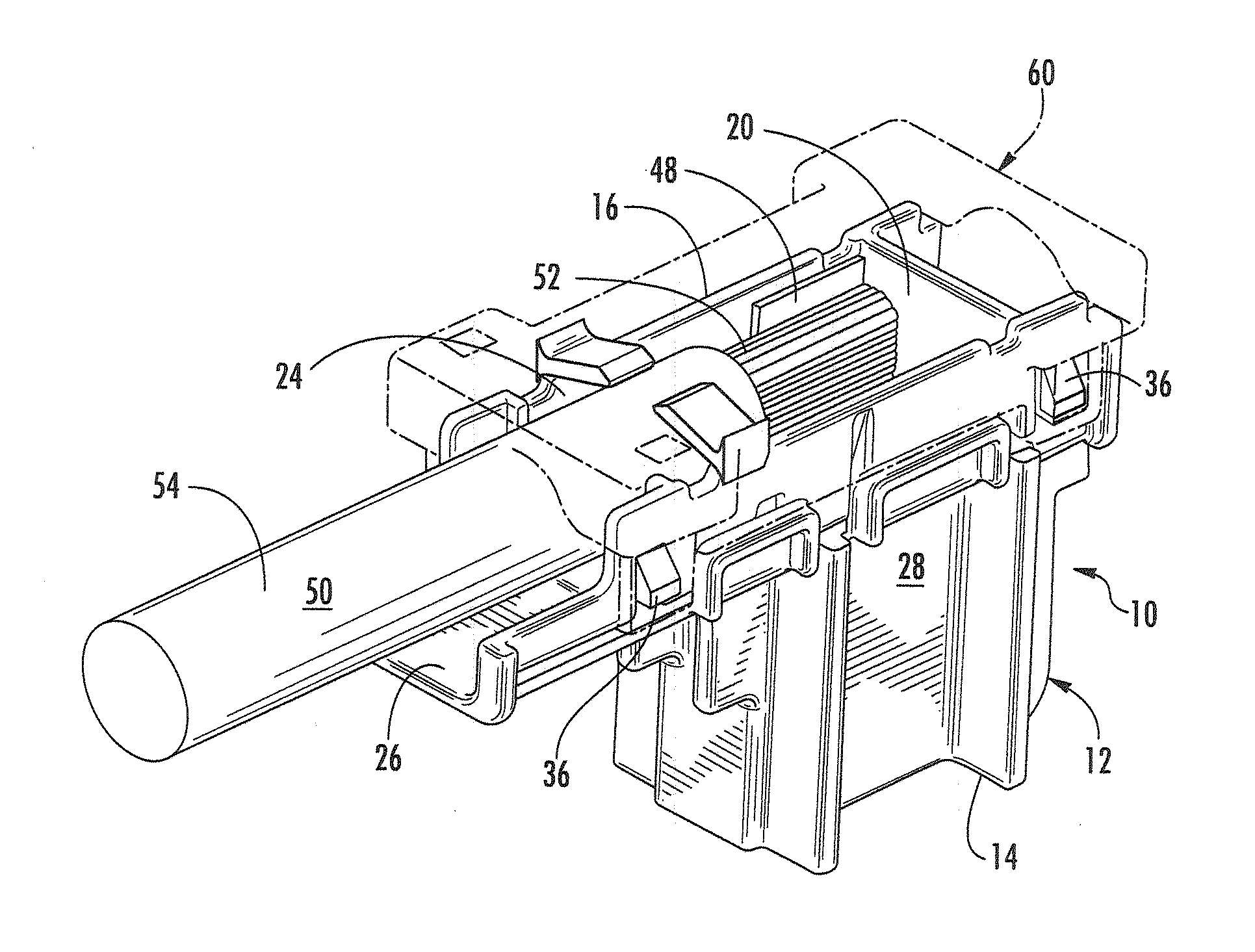
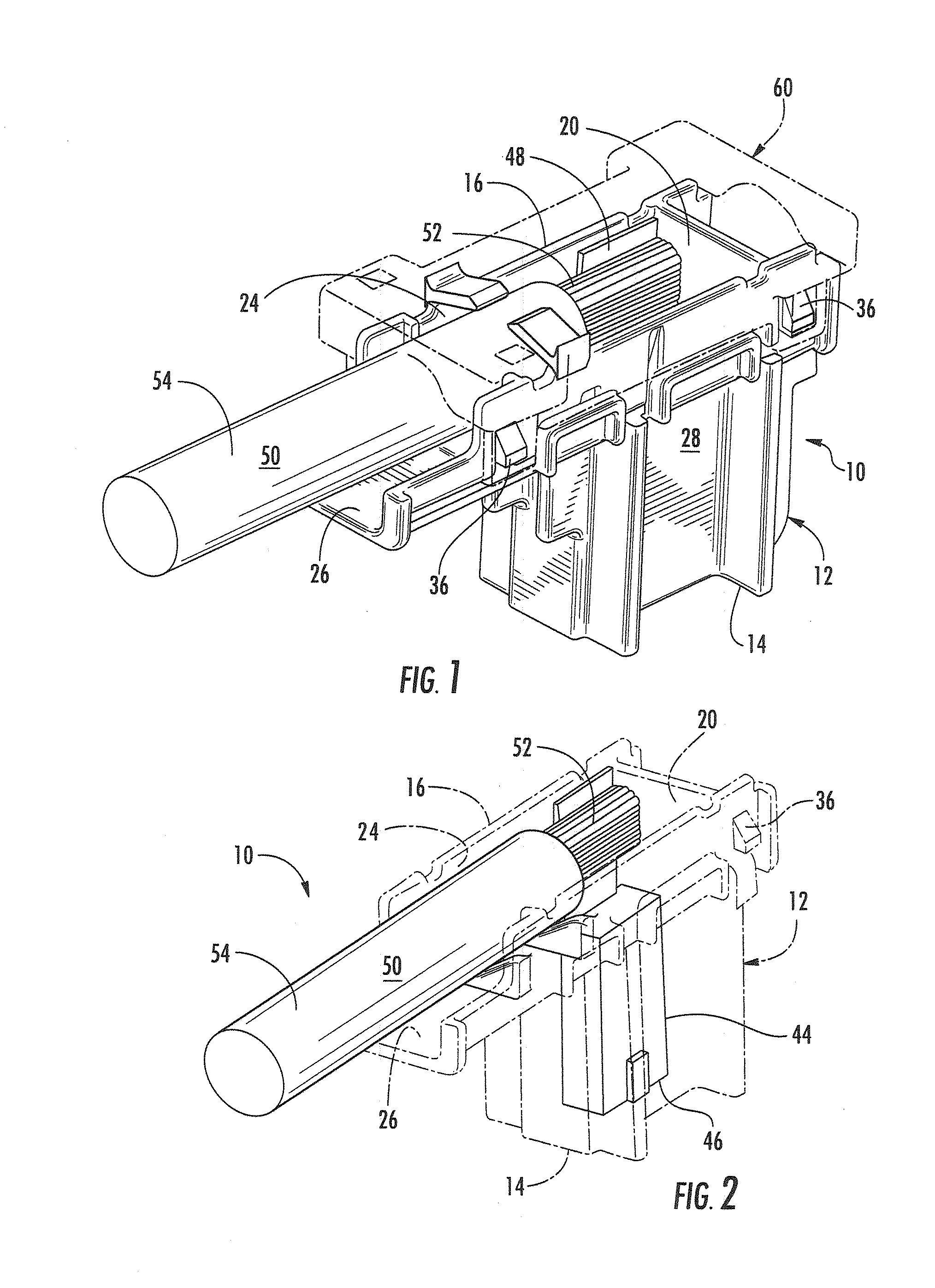
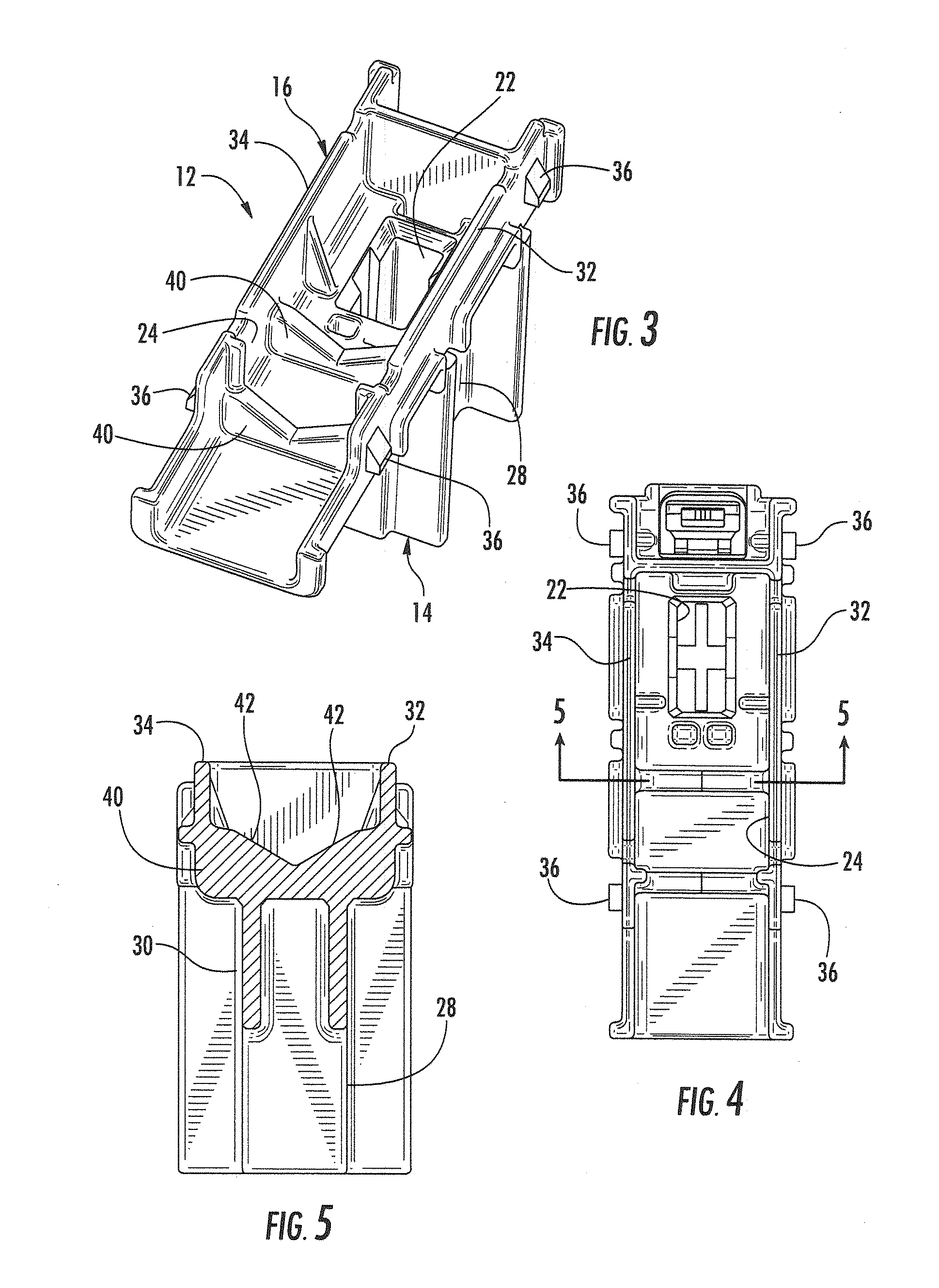
[0028]A variable strain relief connector in accordance with the subject invention is identified generally by the numeral 10 in FIGS. 1-10. The connector 10 includes a housing 12 with opposite front and rear ends 14 and 16 that are spaced apart along a terminal insertion direction and a mating direction. A mating opening 18 is formed at the front end 14 of the housing 12 and an insertion opening 20 is formed at the rear end 16 of the housing 12. A terminal receiving cavity 22 extends from the front end 14 to the rear end 16 of the housing and provides communication between the mating opening 18 and the insertion opening 20. The housing 12 further includes a wire receptacle 24 that is open to the insertion opening 20 at the rear end 16 of the housing 12 and extends transversely from the terminal receiving cavity 22 to a concave wire draw-out opening 26. In other embodiments, however, the wire receptacle 24 may be aligned axially with the terminal receiving cavity 22 and may extend alo...


PUM


Abstract

A connector (10) includes a housing (12) with a terminal receiving cavity (22) and a wire receptacle (24) communicating with the terminal receiving cavity (22). The wire receptacle (24) includes at least one V-shaped wire support (40) for supporting a wire (50) at two circumferentially spaced positions on the wire (50). A cover (60) is mounted to the housing (12) and has at least one resiliently deflectable strain relief beam (70) that biases the wire (50) into the wire receptacle (24).

Description

BACKGROUND[0001]1. Field of the Invention[0002]The invention relates a connector to provide strain relief for large diameter wires, such as high current battery cables, and particularly for such wires that may be subject to variation in outer diameter.[0003]2. Description of the Related Art[0004]A wire includes a conductive core and an insulating coating surrounding the core. The insulation is removed near the end of the wire so that the conductive core can be connected to a terminal fitting, typically by welding, soldering or crimping. The assembly of the wire and the terminal fitting then may be mounted into a housing made of a synthetic resin or other nonconductive material. The wire, the terminal fitting and the housing form a connector that can be connected to a mating connector so that the terminal fitting of the connector is connected electrically to a mating terminal fitting in the mating connector.[0005]Electrical connectors often are used in high vibration environments and...

Claims


Application Information

Patent Timeline
IPC IPC(8): H01R13/58
CPCH01R13/5812H01R13/582
Inventor NAGY, BRIANLANZOTTI, JOSEPH
Owner SUMITOMO WIRING SYST LTD
Why Eureka
Try Eureka