Plug connector with improved strain relief member

a strain relief member and plug connector technology, applied in the direction of coupling device details, coupling device connection, printed circuit, etc., can solve the problem that the conventional simple structure strain relief member is not suitable for us

Inactive Publication Date: 2007-02-15
HON HAI PRECISION IND CO LTD
View PDF1 Cites 14 Cited by
  • Summary
  • Abstract
  • Description
  • Claims
  • Application Information

AI Technical Summary

Benefits of technology

[0007] Accordingly, an object of the present invention is to provide a plug connector with an improved strain relief member to provide enough strain relief to cables thereof.

Problems solved by technology

When formed in 1990, the original goals were limited to define de facto mechanical envelopes within disk drives can be developed to fit compact computer and other small products.
Thus, the conventional simple-structure strain relief member is not suitable to use in such case.

Method used


Image

  • Plug connector with improved strain relief member
  • Plug connector with improved strain relief member
  • Plug connector with improved strain relief member

Examples


Embodiment Construction

[0015] Reference will now be made to the drawing figures to describe the present invention in detail.

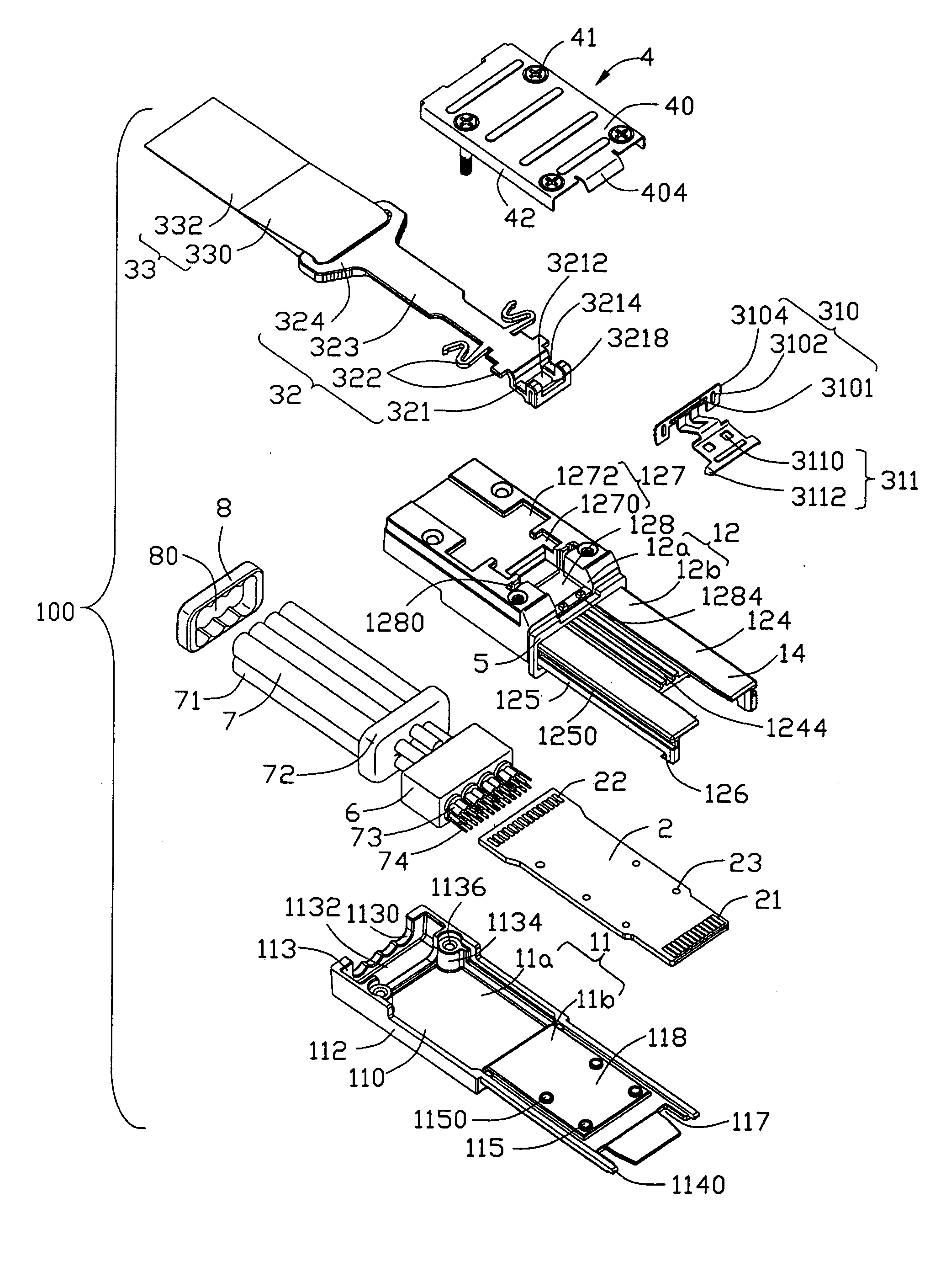
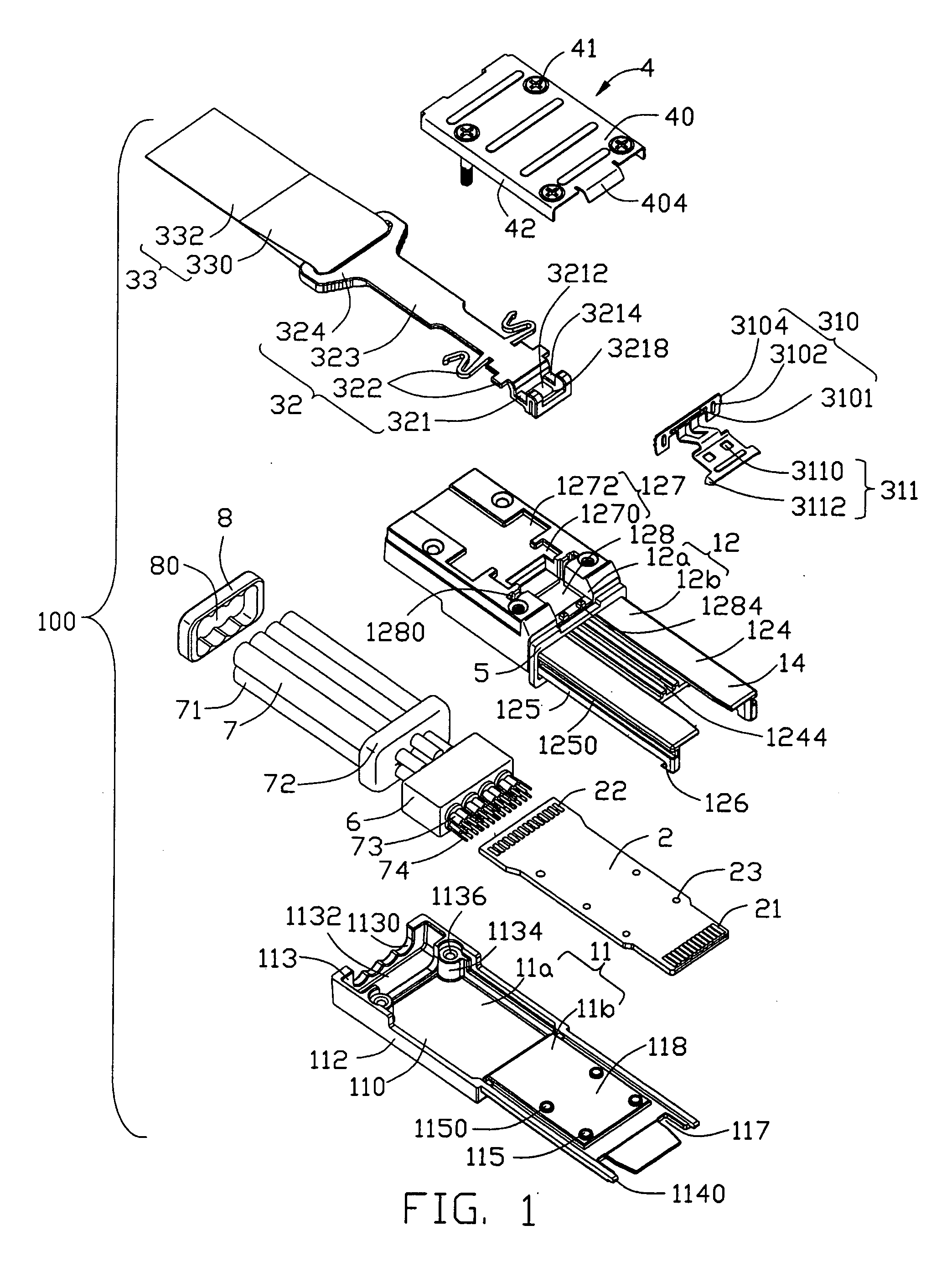
[0016] Referring to FIGS. 1-3, a plug connector 100 in accordance with the present invention comprises a housing 1, a circuit card 2 located in the housing 1, a cable set 7 comprising a plurality of cables 71 respectively electrically connecting with the circuit card 2, a latch mechanism 3 assembled to the housing 1, a metal shell 4 assembled to the housing 1 to partially cover the latch mechanism 3, and a strain relief member 8 electrically connecting with the cables 71.

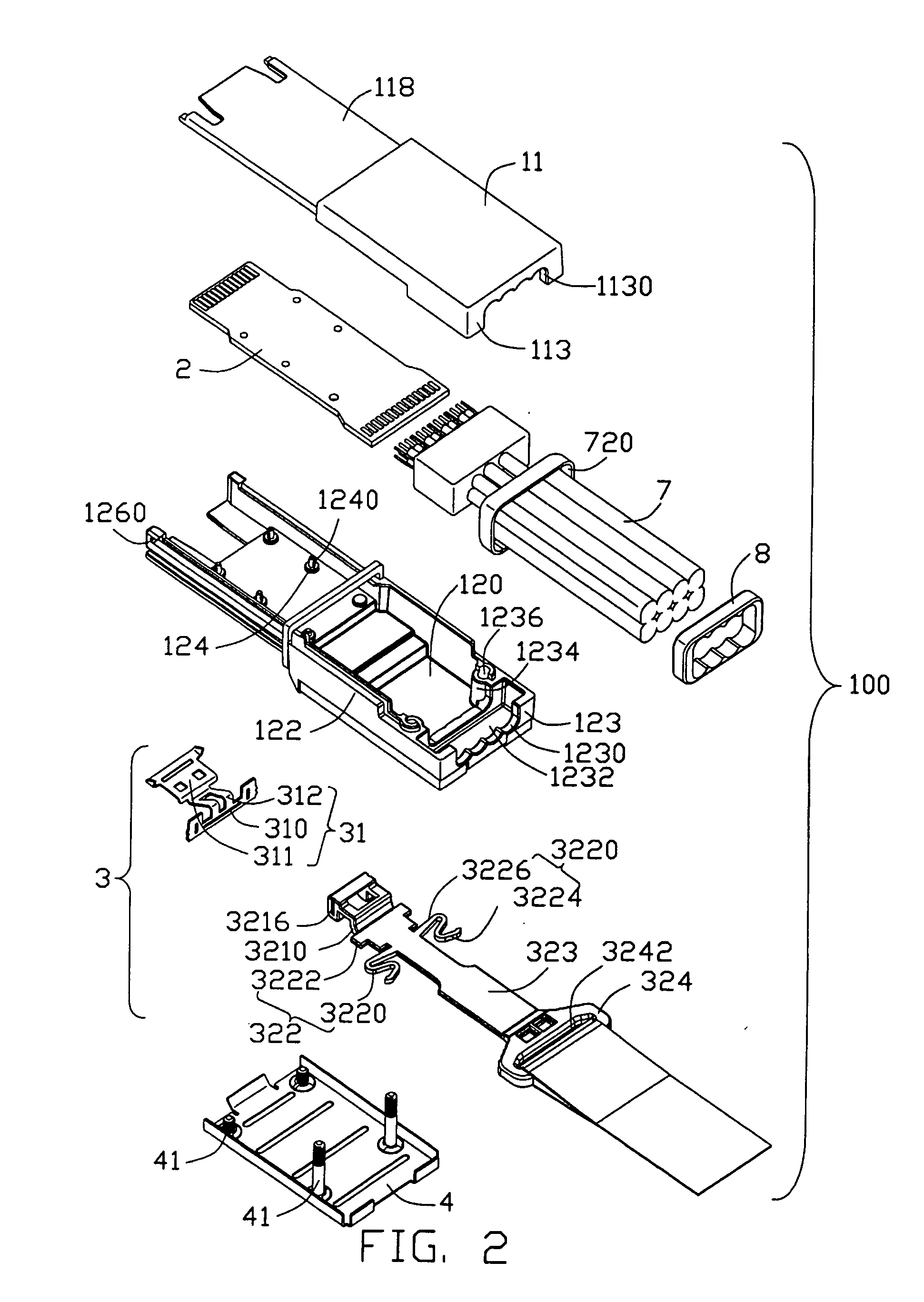
[0017] Please refer to FIGS. 1-2, the housing 1 of the present invention is made of metal material and comprises a base 11, a cover 12 engagble with the base 11 and a receiving space 15 (FIG. 5) formed between the base and the cover 11, 12. The metal housing 1 also comprises a rectangular base portion 13 and an elongated tongue portion 14 extending forwardly from the base portion 13.

[0018] The base 11 comprises a ...


PUM


Abstract

A plug connector (100) includes a housing (1), a PCB (2) received in the housing, a cable set (7) electrically connecting with the PCB, a pulling member (32) moveable relative to the housing in a horizontal direction, a latch member (31) discrete from the pulling member and assembled to the housing for latch with a complementary connector, and a pull tape (33) discrete from the pulling member and assembled to the pulling member. The cable set includes a plurality of conductors (73, 74) connecting with the PCB, a metal braiding layer (72) forming a space and an outer jacket surrounding the metal braiding layer. A strain relief member (8) is assembled to the cable set and surrounded by the metal braiding layer.

Description

CROSS-REFERENCE TO RELATED APPLICATIONS [0001] The present invention is a CIP (continuation-in-part) of U.S. patent application Ser. No. 11 / 201,521 filed on Aug. 11, 2005. Furthermore, t his application is related to U.S. patent application Ser. No. 11 / 201,521 filed on Aug. 11, 2005 and entitled “CABLE CONNECTOR ASSEMBLY WITH LATCHING MECHANISM”, U.S. patent application Ser. No. 11 / 201,461 filed on Aug. 11, 2005 and entitled “CABLE CONNECTOR ASSEMBLY WITH LATCHING MECHANISM”, U.S. patent application Ser. No. 11 / 268,906 filed on Nov. 8, 2005 and entitled “CABLE CONNECTOR ASSEMBLY WITH LATCHING MECHANISM”, U.S. patent application Ser. No. 11 / 268,902 filed on Nov. 8, 2005 and entitled “JUXTAPOSED CABLE CONNECTOR ASSEMBLIES”, and U.S. patent application Ser. No. 11 / 322,692 filed on Dec. 30, 2005 and entitled “STACKED CONNECTOR ASSEMBLY”, U.S. patent application Ser. No. 11 / 213,048 filed on Aug. 26, 2005 and entitled “CABLE CONNECTOR ASSEMBLY WITH EMI GASKET”, and U.S. patent application...

Claims


Application Information

Patent Timeline
Patent Type & Authority Applications(United States)
IPC IPC(8): H01R13/58
CPCH01R13/6335H01R13/6275
Inventor WU, JERRY
Owner HON HAI PRECISION IND CO LTD
Why Eureka
Try Eureka