Fiber optic terminal assembly

a technology of fiber optic terminals and drop terminals, applied in the field of fiber drop terminals, can solve the problems of large fdts, generally unsuitable for installation, large fdts are relatively expensive to produce, and are generally less convenient to transport, install, and service., and achieve the effect of improving the strain reli

Active Publication Date: 2009-03-05
CORNING OPTICAL COMM LLC
View PDF99 Cites 106 Cited by
  • Summary
  • Abstract
  • Description
  • Claims
  • Application Information

AI Technical Summary

Benefits of technology

[0047]FIG. 35 is a perspective view of a strain relief device adapted for use with an opening in an FDT, such as the opening for passage of the distribution cable in the FDT of FIG. 25, illustrating the generally frustoconical shape and the three ribs along the frustoconical surface to provide improved strain relief for the distribution cable;

Problems solved by technology

However, such FDTs are large and are generally not desirable for installation on each floor or other section of an MDU based upon the size of their footprint, visibility, and other considerations.
Such large FDTs are also relatively expensive to produce and are generally less convenient to transport, install, and service.

Method used


Image

  • Fiber optic terminal assembly
  • Fiber optic terminal assembly
  • Fiber optic terminal assembly

Examples


Embodiment Construction

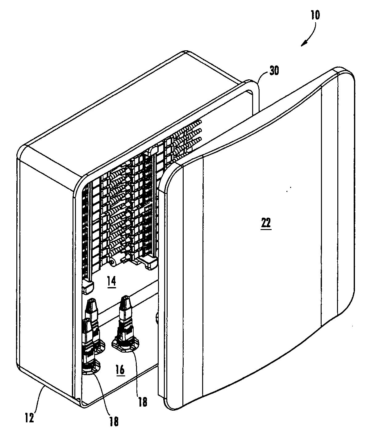
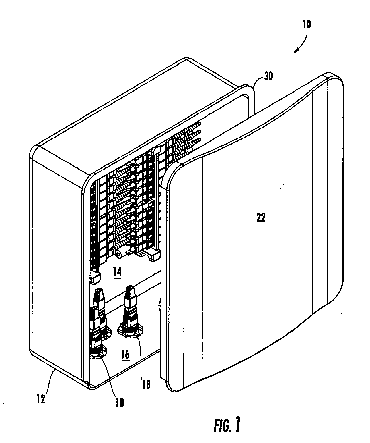
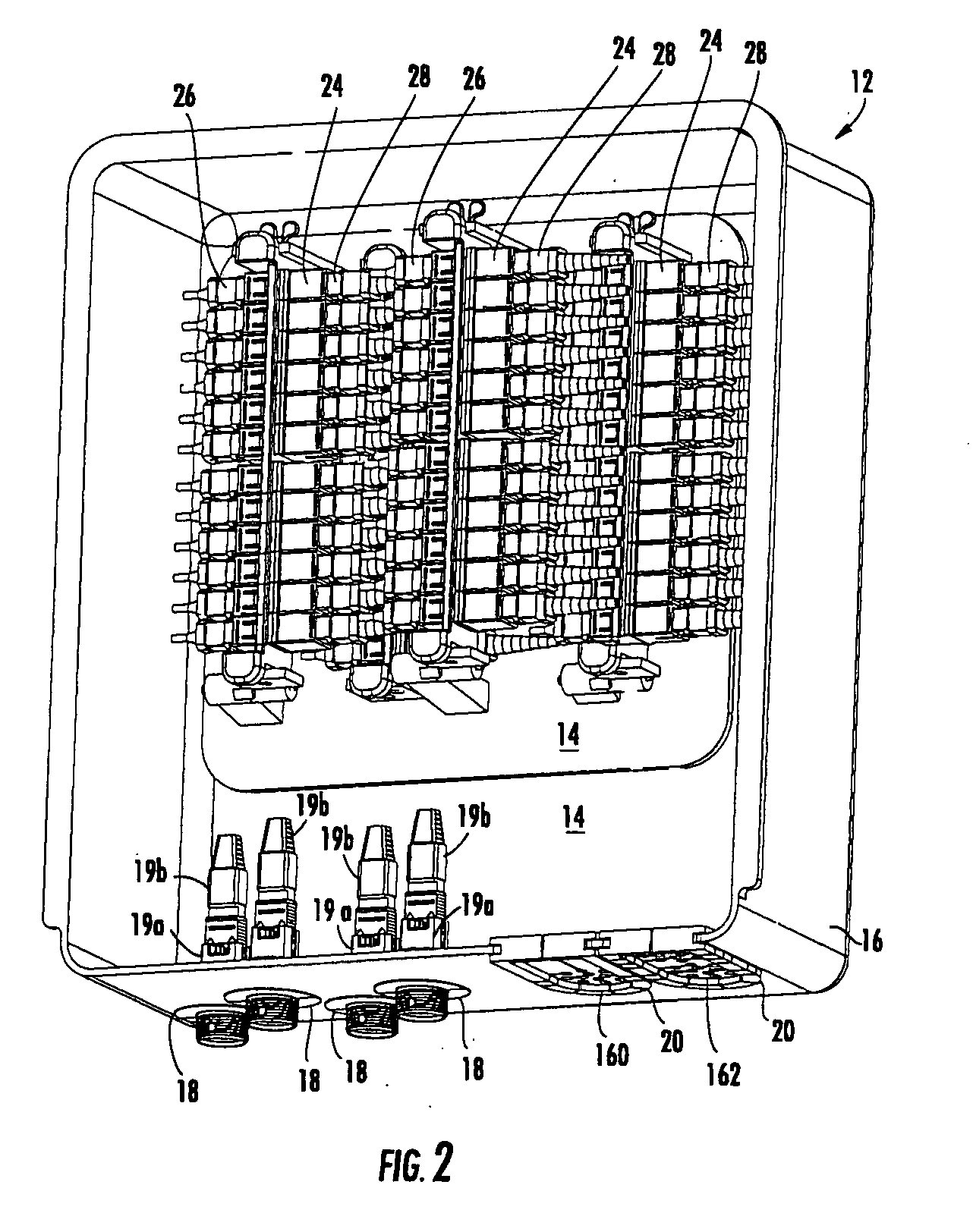
[0092]The present invention now will be described more fully hereinafter with reference to the accompanying drawings, in which some, but not all embodiments of the invention are shown. Indeed, the invention may be embodied in many different forms and should not be construed as limited to the embodiments set forth herein; rather, these embodiments are provided so that this disclosure will satisfy applicable legal requirements. Although apparatus and methods for providing optical connectivity between optical fibers of distribution cables and drop cables are described and shown in the accompanying drawings with regard to specific types of fiber drop terminals, also known as fiber distribution terminals, (collectively, “FDTs”), it is envisioned that the functionality of the various apparatus and methods may be applied to any now known or hereafter devised enclosures and related fiber optic network equipment in which it is desired to provide optical connections between optical fibers of ...


PUM


Abstract

There is provided fiber drop terminal (“FDT”) assemblies for providing selective connections between optical fibers of distribution cables and optical fibers of drop cables, such as in multiple dwelling units. The FDT assemblies include a base and a cover that define a tongue and groove that selectively engage to seal the base and cover. The FDT assemblies also include a mounting plate for mounting of the base and cover, as well as a mounting plate extension for mounting of a skirt. The skirt provides slack storage for drop cables exiting the FDT. The components of the FDT assembly are selectively interlockable to prevent unauthorized access to the interior cavity of the base and cover and to the slack storage area of the skirt.

Description

CROSS-REFERENCE TO RELATED APPLICATION[0001]The present application claims priority pursuant to 35 U.S.C. 119(e) to U.S. Provisional Application, Ser. No. 60 / 967,559, filed Sep. 5, 2007.BACKGROUND OF THE INVENTION[0002]1. Field of the Invention[0003]The present invention is related to fiber drop terminals, and more particularly, to fiber drop terminal assemblies including a sealing cover and / or skirt.[0004]2. Description of Related Art[0005]To provide improved performance to subscribers, fiber optic networks are increasingly providing optical fiber connectivity directly to the subscribers. As part of various fiber-to-the-premises (FTTP), fiber-to-the-home (FTTH), and other initiatives (generally described as FTTX), such fiber optic networks are providing the optical signals from distribution cables through local convergence points (“LCPs”) to fiber optic cables, such as drop cables, that are run directly or indirectly to the subscribers' premises. Such optical connectivity is increa...

Claims


Application Information

Patent Timeline
Patent Type & Authority Applications(United States)
IPC IPC(8): G02B6/24
CPCG02B6/3897G02B6/4471G02B6/4452G02B6/4442
Inventor COX, TERRY DEANRODRIGUEZ, DIANARASMUSSEN, MICHAEL HEATHSTRAUSE, KEVIN LEE
Owner CORNING OPTICAL COMM LLC
Why Eureka
Try Eureka