Cable assembly with unique strain relief means

a cable and strain relief technology, applied in the direction of electrical apparatus, connection, coupling device connection, etc., can solve the problems of cable damage, cable damage, electrical performance degradation, etc., and achieve the effect of improving strain relief and low cos

Inactive Publication Date: 2006-11-02
HON HAI PRECISION IND CO LTD
View PDF11 Cites 4 Cited by
  • Summary
  • Abstract
  • Description
  • Claims
  • Application Information

AI Technical Summary

Benefits of technology

[0007] Accordingly, an object of the present invention is to provide a cable assembly with improved strain relief means with aid of time spare and low cost.

Problems solved by technology

However, when the strain relief 56 is secured to shell means 18 enclosing the connector housing 18, the cable may suffer too great external force that could damage the cable and render degradation in electrical performance.
Moreover, such design is unfavorable for high speed application because it ignores Electro Magnetic Interference (EMI) leakage between the strain relief 56 and the shell means 18.
In addition, the process of crimping the strain relief 56 to the cable is completed manually, and therefore is imprecise and time consuming.

Method used


Image

  • Cable assembly with unique strain relief means
  • Cable assembly with unique strain relief means
  • Cable assembly with unique strain relief means

Examples


Embodiment Construction

[0020] Reference will now be made to the drawing figures to describe the present invention in detail.

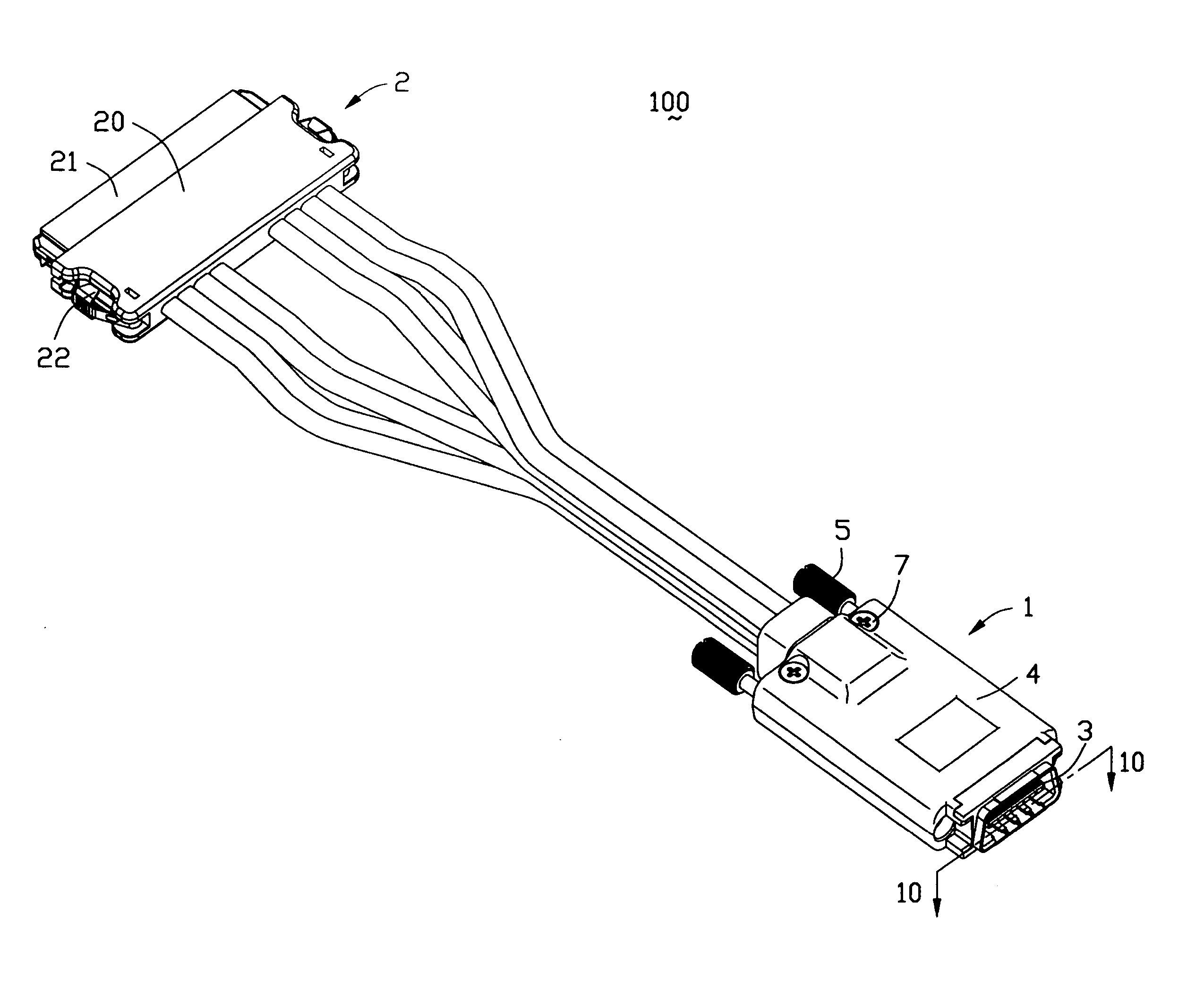
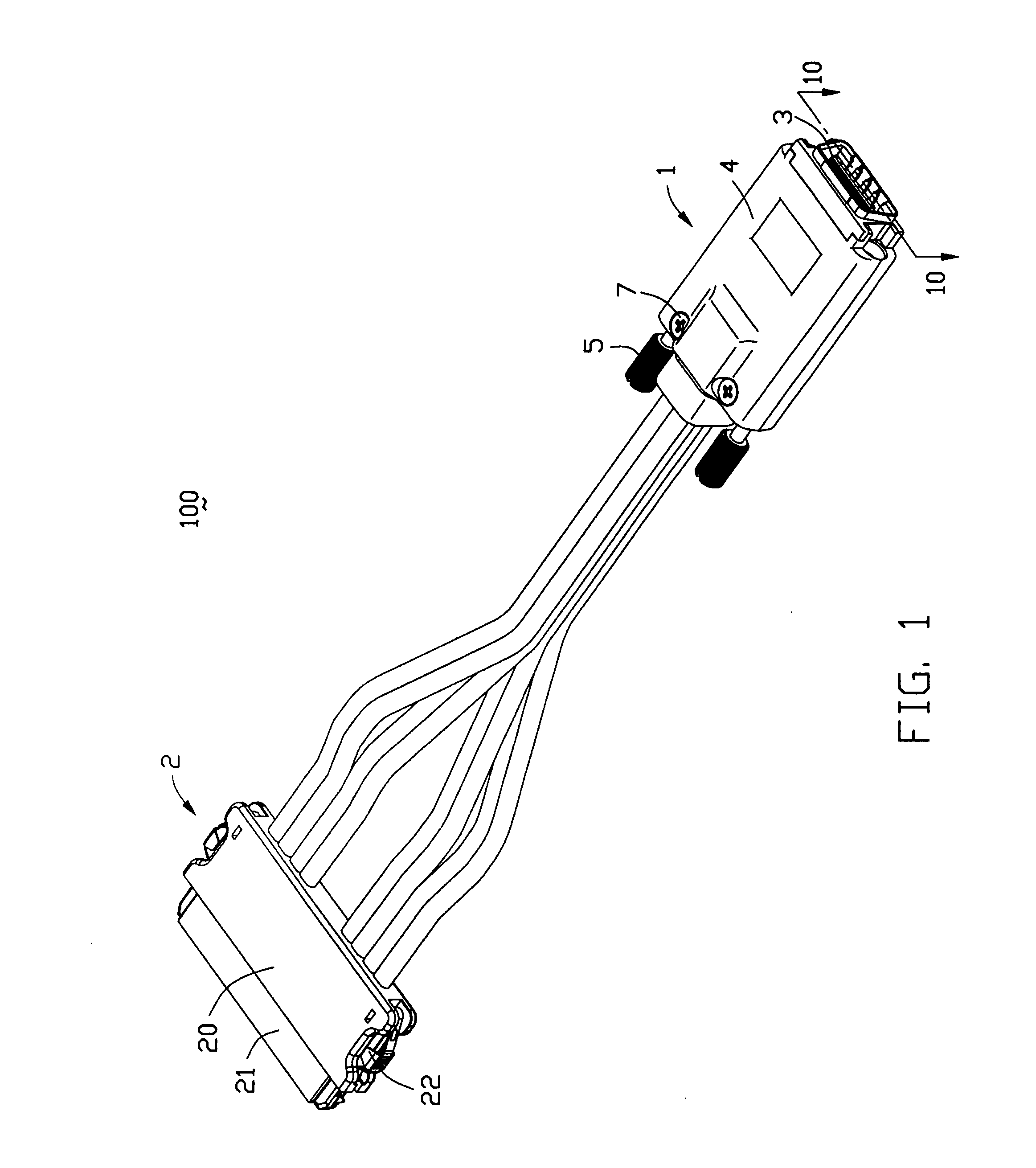
[0021] Referring to FIGS. 1-4, a cable assembly 1 in accordance with the present invention is electrically connected with a complementary connector 2 to form an electrical assembly 100. In the preferred embodiment, the complementary connector 2 is a Serial Advanced Technology Attachment (ATA) II cable end connector. The complementary connector2 comprises a mating portion 21, a plurality of terminals received in the mating portion 21, a plurality of cables 32 electrically connecting with the mating portion 21, and a molded cover 20 molded with the junctions between the cables 32 and the terminals. A pair of latches are pivotally assembled to the molded cover 20 for latching with an outer device.

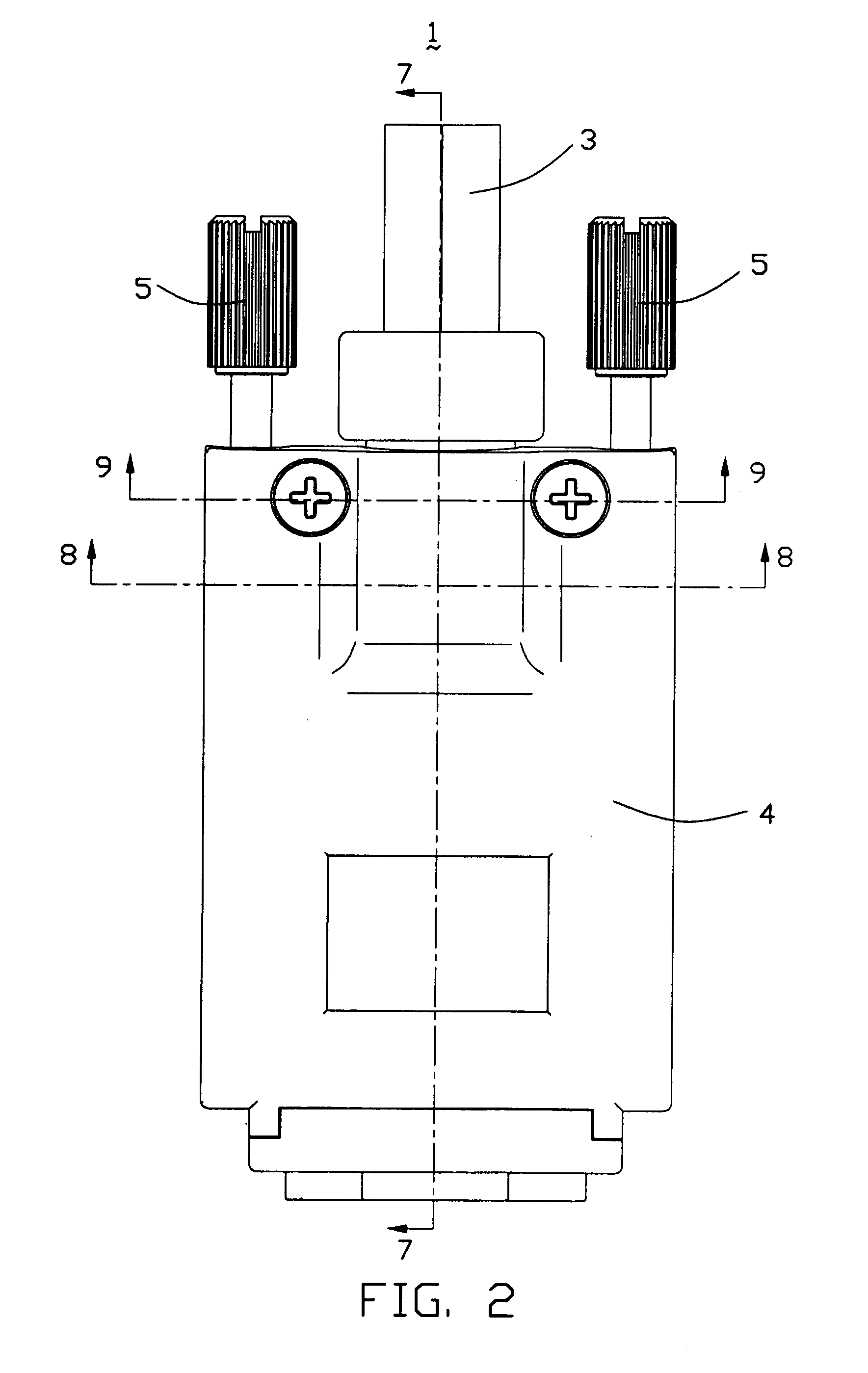
[0022] The cable assembly 1 comprises a connector module 3, a die-cast cover 4 enclosing the connector module 3, a pair of fastening members 5 assembled to the die-cast cover 4 for disengagin...


PUM


Abstract

A cable assembly (1) includes a connector module (3), a first cover-half (41) and a second cover-half (42) assembled to the first cover-half to enclose the connector module therebetween. The connector module includes an insulative housing (33), a number of contacts (35) retained in the insulative housing, a printed circuit board (34) assembled to the insulative housing and electrically connecting with the contacts, a number of cables (32) electrically connecting with the printed circuit board to form a number of junctions, and strain relief means (31). The strain relief means includes a main portion (310) molded with the junctions, a strain relief section (312) molded with the cables and interferentially received in a receiving hole (13) formed between the first and second cover-halves.

Description

BACKGROUND OF THE INVENTION [0001] 1. Field of the Invention [0002] The present invention generally relates to a cable assembly, and more particularly to a high speed cable assembly. [0003] 2. Description of Related Art [0004] When a cable or the like is terminated by an electrical connector to form a cable assembly, strain relief means is provided to minimize forces exerted on the junctions between conductors of the cable and contacts of the electrical connector. Strain relief means assembled to the cable and the electrical connector requires proper compression of the cable and holds the cable firmly. [0005] U.S. Pat. No. 5,383,796 issued to Molex on Jan. 24, 1995 discloses a traditional metal strain relief structure 56 crimped to a cable manually. The strain relief 56 includes a center section 6 adapted to embrace one side of the cable, a pair of wing sections 62 extending from the center section 60 and having screw-receiving holes 58 in alignment with screw posts 38 defined on a ...

Claims


Application Information

Patent Timeline
Patent Type & Authority Applications(United States)
IPC IPC(8): H01R13/58
CPCH01R9/034H01R13/512H01R13/6658H01R13/59H01R13/5845H01R13/65914
Inventor WU, JERRY
Owner HON HAI PRECISION IND CO LTD
Why Eureka
Try Eureka