Cable connector assembly with improved strain relief and method of making the same

Inactive Publication Date: 2015-12-10
FOXCONN INTERCONNECT TECHNOLOGY LIMITED
View PDF11 Cites 1 Cited by
  • Summary
  • Abstract
  • Description
  • Claims
  • Application Information

AI Technical Summary

Benefits of technology

[0007]Accordingly, an object of the present invention is to pro

Problems solved by technology

Strain-reliefs that present a solid structure, i.e., substantially inelastic when being pressed forwardly by an outer cover during assembling the latter, may cause problem in that the strain-relief is pressed by the outer cover and therefore tend to move forwardly, thus

Method used


Image

  • Cable connector assembly with improved strain relief and method of making the same
  • Cable connector assembly with improved strain relief and method of making the same
  • Cable connector assembly with improved strain relief and method of making the same

Examples


Embodiment Construction

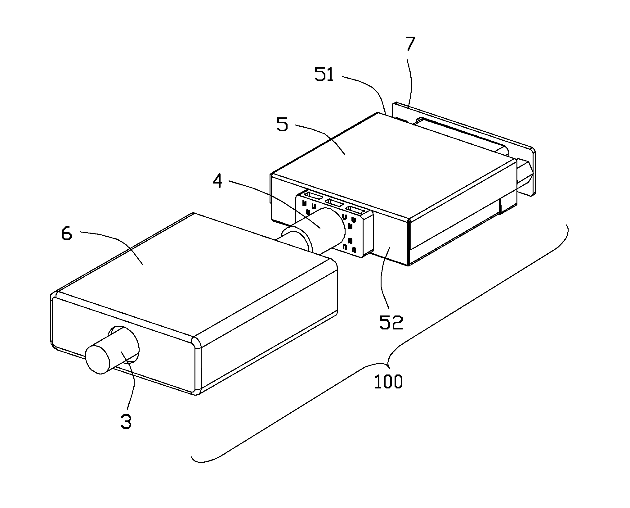
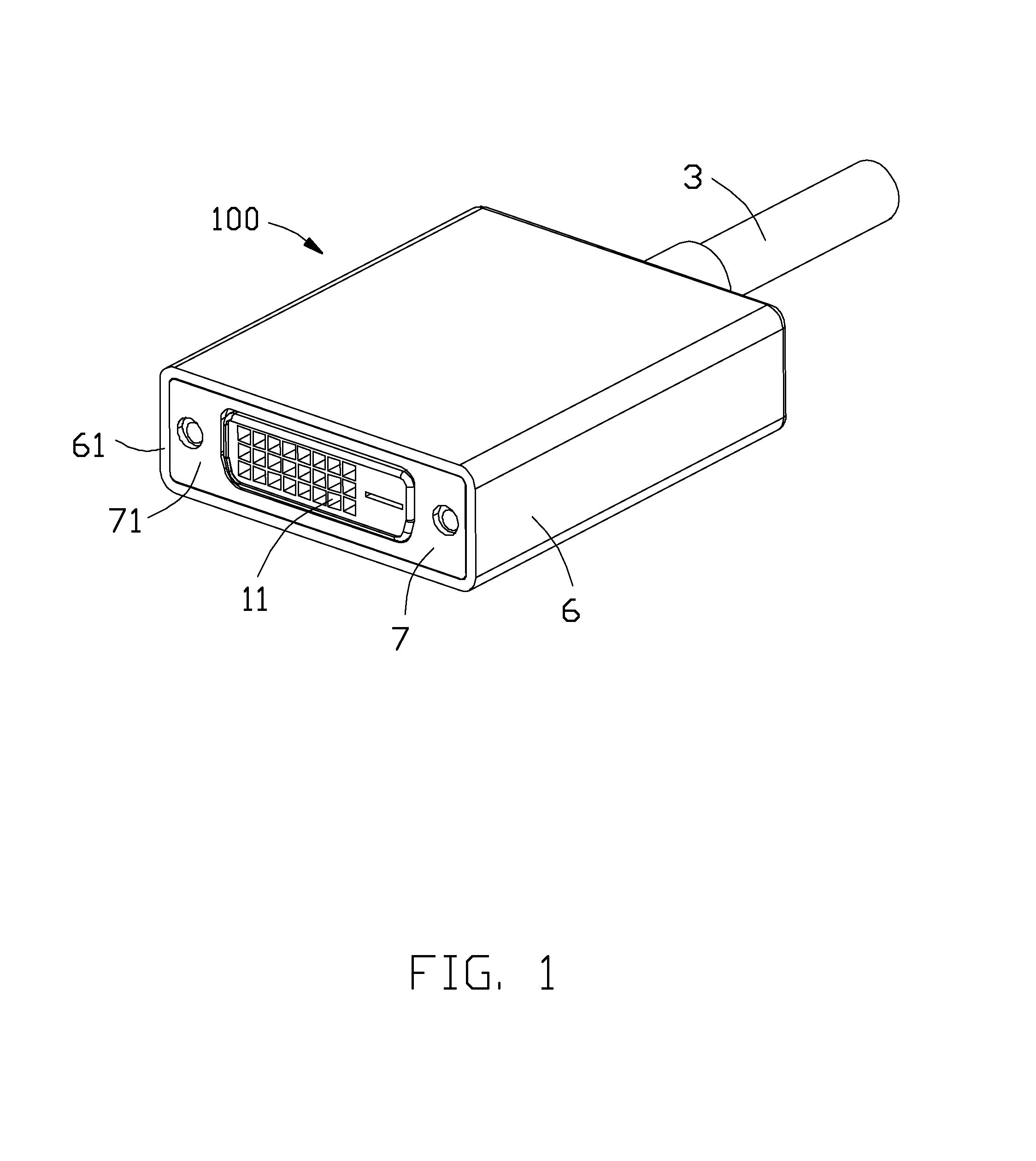
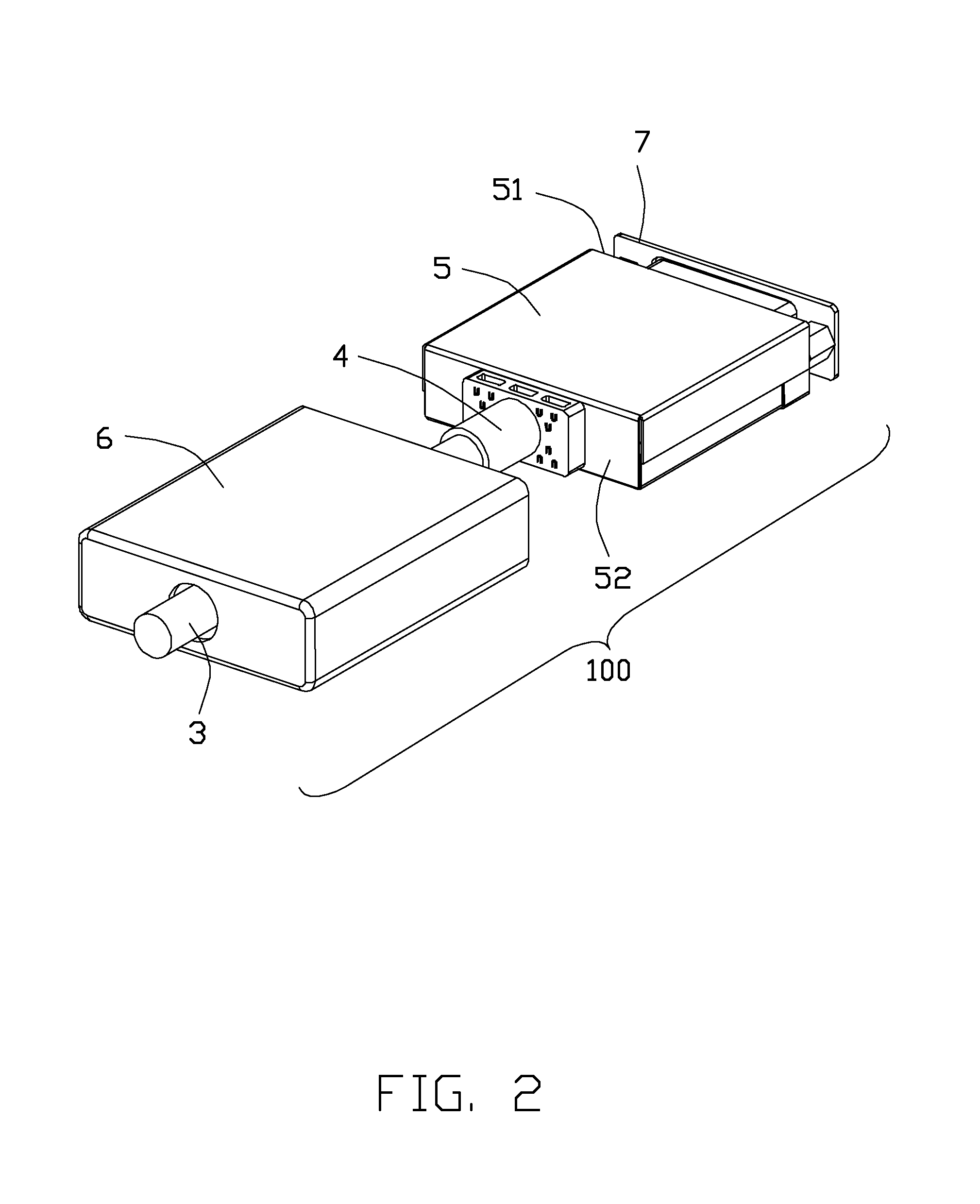
[0018]Referring to FIGS. 1 and 7, a cable connector assembly 100 in accordance with the present invention comprises a connector 1 for mating with a complementary connector (not shown), a printed circuit board 2 having a front portion 21 and a rear portion 22, a cable 3 electrically connected to the rear portion 22 of the printed circuit board 2, a strain relief 4 disposed outside of the cable 3, a shell 5 shielding the printed circuit board 2, an outer case 6 enclosing the shell 5, and a metal plate 7 mounted on the connector 1. The connector 1 comprises a body portion 10, a plurality of conductive contacts (not shown) electrically connected with the front portion 21 of the printed circuit board 2, and a plurality of contact slots 11 for receiving the conductive contacts. The metal plate 7 comprises a mating surface 71 and an opening 72 for the connector 1 to extend through.

[0019]The cable 3 comprises a plurality of conductive wires 31 and an outer layer 32 enclosing the conductive ...


PUM

PropertyMeasurementUnit
Lengthaaaaaaaaaa
Strain pointaaaaaaaaaa

Abstract

A cable connector assembly includes a connector, a printed circuit board having a rear portion, a cable connected to the rear portion, a strain relief having a main portion, a shell having a front wall and a rear wall, an outer case enclosing the shell and having a front end face and a rear end face, wherein the main portion is disposed between the rear wall and the rear end face, and the main portion comprises at least one through hole. A method of assembling a cable connector assembly, the cable connector assembly including a connector, a printed circuit board, and a cable, the method comprising the steps of: over-molding a strain relief with the cable to have a main portion defining at least one through hole; disposing the printed circuit board in a shell; and mounting an outer case forwardly over the shell to press the strain relief.

Description

BACKGROUND OF THE INVENTION[0001]1. Field of the Invention[0002]The present invention relates to a cable connector assembly and method of making the same, and more particularly to an improved strain relief thereof[0003]2. Description of Related Art[0004]U.S. Pat. No. 7,648,372, issued on Jan. 19, 2010, discloses a cable connector assembly comprising a connector, a printed circuit board having a front portion and a rear portion, a cable electrically connected to the rear portion of the printed circuit board, a strain relief disposed outside of the cable, an inner case enclosing the printed circuit board, and an outer case enclosing the inner case. The strain relief comprises a main portion and an extending portion connected with the main portion. The main portion defines a pair of gaps to clamp the rear portion of the printed circuit board.[0005]U.S. Patent Application Publication No. 2013 / 0189872, published on Jul. 25, 2013, discloses a cable assembly including an inner strain-relie...

Claims


Application Information

Patent Timeline
IPC IPC(8): H01R13/58H01R43/20H01R13/66
CPCH01R13/5845Y10T29/49149H01R43/205H01R13/665H01R13/6581H01R13/6658
Inventor WU, JERRYCHEN, JUNMENG, FAN-BO
Owner FOXCONN INTERCONNECT TECHNOLOGY LIMITED
Why Eureka
Try Eureka