Slip Ring Contact Coaxial Connector

Inactive Publication Date: 2012-03-15
COMMSCOPE TECH LLC
View PDF11 Cites 55 Cited by
  • Summary
  • Abstract
  • Description
  • Claims
  • Application Information

AI Technical Summary

Problems solved by technology

The compression element is typically supplied loose with the coaxial connector prior to installation, which creates a loss and/or damage risk for the compression element.
Although a corrugated outer conductor coaxial cable provides a suitable outer diameter grip surface for a user during the flaring procedure, the smooth outer diameter of a smooth wall outer conductor coaxial cable may be difficult to easily grip during flaring.
Further, smooth wall outer conductor cables provide inherent materials cost and cable weight advantages compared to corrugated outer conductor coaxial ca

Method used


Image

  • Slip Ring Contact Coaxial Connector
  • Slip Ring Contact Coaxial Connector
  • Slip Ring Contact Coaxial Connector

Examples


Embodiment Construction

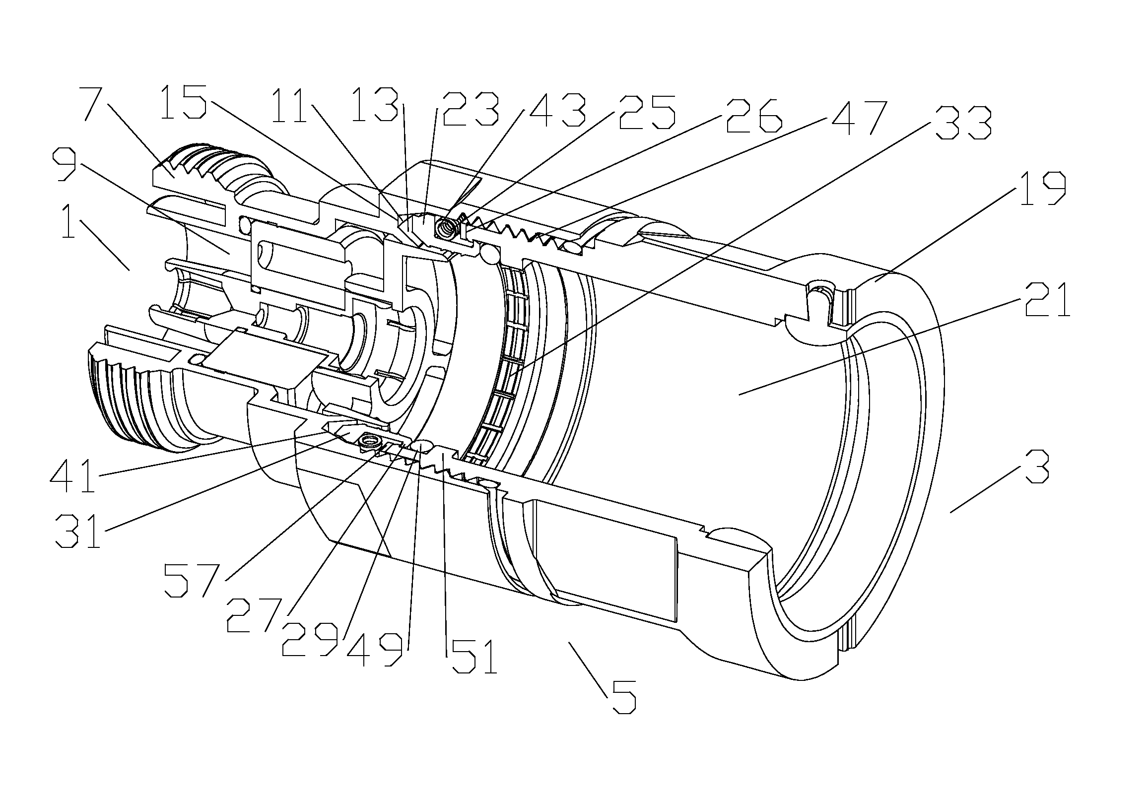
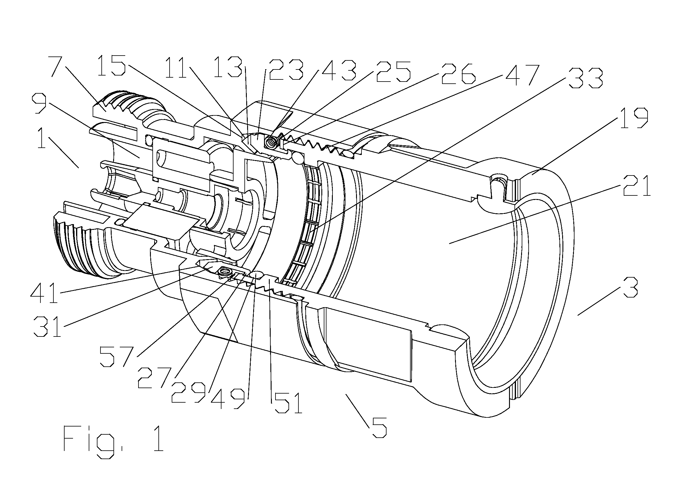
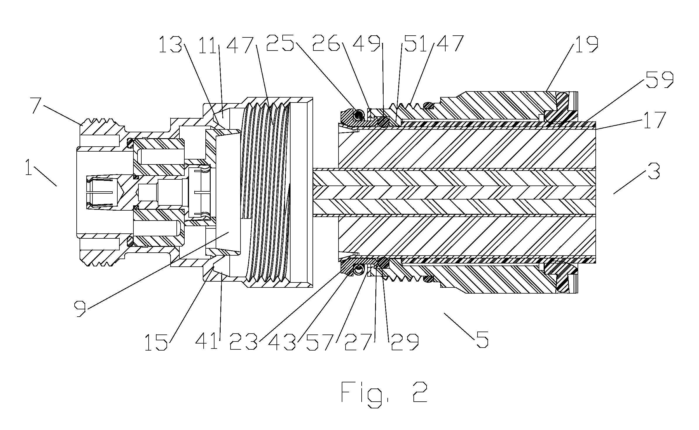
[0035]One skilled in the art will appreciate that the connector end 1 and the cable end 3 are descriptors used herein to clarify longitudinal locations and / or contacting interrelationships between the various elements of the coaxial connector(s). In addition to the identified positions in relation to adjacent elements along the coaxial connector longitudinal axis, each individual element has a connector end side and a cable end side, i.e. the sides of the respective element that are facing the respective connector end 1 and the cable end 3 of the coaxial connector 5. A first embodiment of a coaxial connector, as shown in FIGS. 1-6, includes a connector body 7 provided with a connector body bore 9. As best shown in FIG. 2, an annular coupling groove 11 provided in the connector body bore 3 is open to a cable end 3 of the connector body 7. A clamp sidewall 13 of the coupling grove 11 is angled inward from a bottom 15 of the coupling groove 11, dimensioned as a seat against which a lea...


PUM


Abstract

A coaxial connector with a connector body is provided with a connector body bore. An annular coupling groove is provided in the connector body bore open to a cable end of the connector body. A clamp sidewall of the coupling grove is angled inward from a bottom of the coupling groove. A slip ring seated within the coupling body bore is provided with a grip surface. An annular compression body is positioned between the slip ring and a compression surface of the coupling body. The connector body and the coupling body are coupled together via threads. The slip ring is dimensioned for axial advancement of the coupling body along the threads to exert a compression force against the compression body to clamp a leading edge of the outer conductor between the slip ring and the clamp sidewall.

Description

CROSS REFERENCE TO RELATED APPLICATIONS[0001]This application claims the benefit of U.S. Provisional Patent Application Ser. No. 61 / 184,573 “Coaxial Connector for Solid Outer Conductor Coaxial Cable” filed Jun. 5, 2009 by Nahid Islam and Al Cox, currently pending and hereby incorporated by reference in its entirety.BACKGROUND OF THE INVENTION[0002]1. Field of the Invention[0003]The invention relates to electrical connectors for coaxial cable. More particularly the invention relates to a coaxial connector with a slip ring contact which provides a grip and clamp outer conductor electro-mechanical interconnection.[0004]2. Description of Related Art[0005]A positive stop type coaxial connector, for example as disclosed in commonly owned U.S. Pat. No. 6,793,529 titled: “Coaxial Connector with Positive Stop Clamping Nut Attachment”, by Larry Buenz, issued Sep. 21, 2004, hereby incorporated by reference in its entirety, has a connector body and a back nut configured for threaded interconnec...

Claims


Application Information

Patent Timeline
IPC IPC(8): H01R9/05
CPCH01R9/0521H01R13/5205H01R2103/00H01R24/40H01R24/564H01R13/65802H01R13/6584H01R9/05
Inventor ISLAM, NAHIDCOX, AL
Owner COMMSCOPE TECH LLC
Why Eureka
Try Eureka