
Scalable VLAN grouping in a provider Metro Ethernet
a technology of metro ethernet and scalable virtual local area network, which is applied in the field of computer networks, can solve the problems of inability to properly scale, drawbacks of increasing the number of c-vlans per man, and inability to address potential scalability problems,
- Summary
- Abstract
- Description
- Claims
- Application Information
AI Technical Summary
Benefits of technology
Problems solved by technology
Method used
Image

Examples
Embodiment Construction
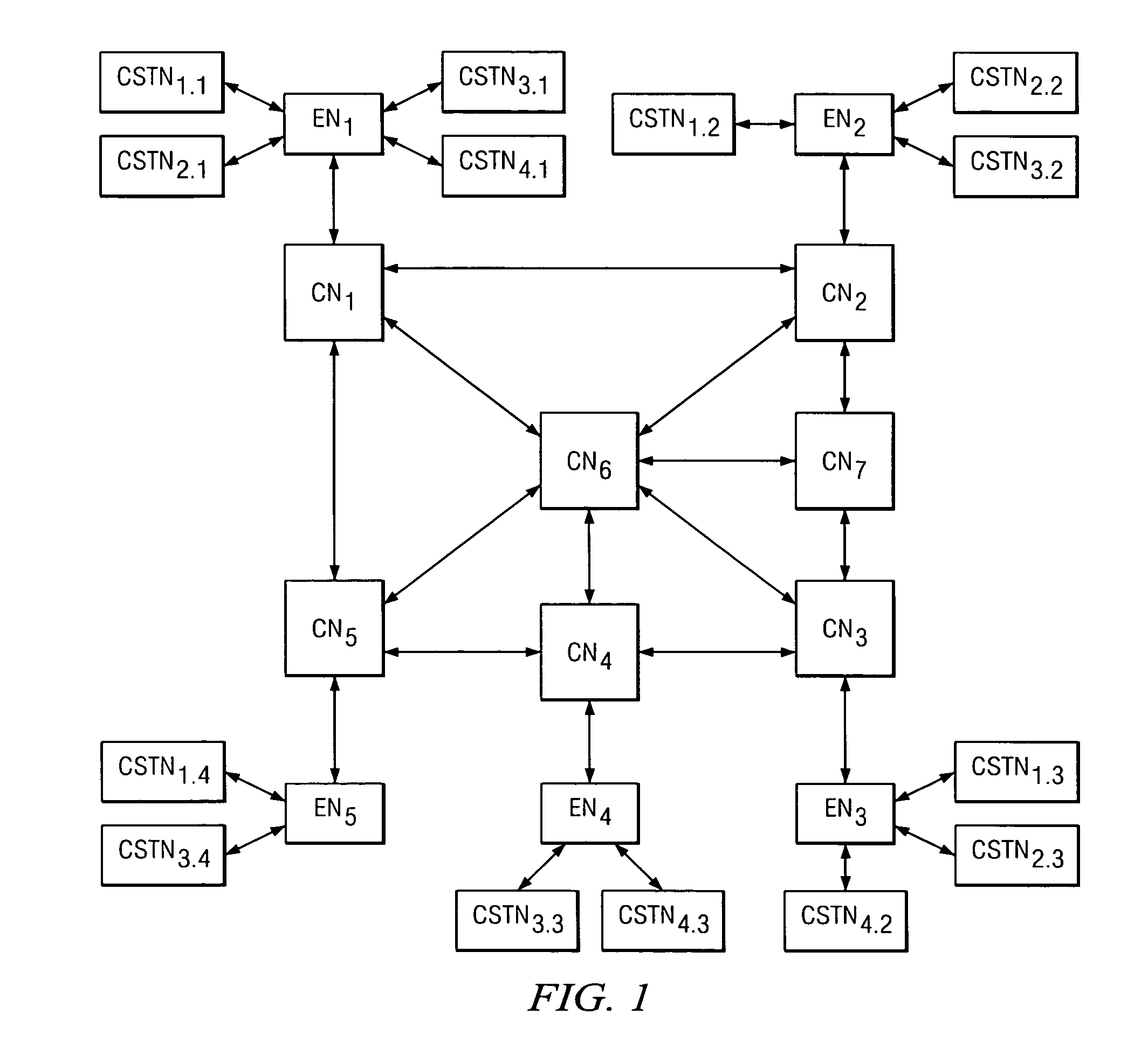
[0015]FIG. 1 illustrates a block diagram of a system 10 into which the preferred embodiments may be implemented. System 10 generally represents a Metro Ethernet network that includes a number of Metro nodes, which also may be referred to as Ethernet switches. As introduced earlier in the Background Of The Invention section of this document, some of these nodes are typically described as edge nodes or core nodes based on their location in the network; by way of example, system 10 includes seven core nodes CN1 through CN7, where the set of core nodes is often referred to as the core network. Certain ones of the core nodes are connected to corresponding edge nodes, where in the example of FIG. 1 this includes five edge nodes EN1 through EN5, each connected to a respective core node CN1 through CN5. Note that the connections between nodes may be referred to in various manners and may be achieved in various ways, but in any event they permit bi-directional communication between each grou...
PUM
 Abstract
Description
Claims
Application Information