Method and an installation for obtaining carbon bodies from carbon-precursor bodies

a technology of carbon precursors and carbon bodies, applied in the direction of material analysis, instruments, phase/state change investigation, etc., can solve the problem of inability to use sensors, and achieve the effect of saving costs and duration

Active Publication Date: 2008-08-12
MESSIER BUGATTI INC +1
View PDF11 Cites 13 Cited by
  • Summary
  • Abstract
  • Description
  • Claims
  • Application Information

AI Technical Summary

Benefits of technology

[0010]An object of the invention is to provide a method and an installation enabling carbon bodies to be obtained while making very significant savings in terms of cost and duration.
[0037]The or each first sensor is preferably a thermocouple sensor housed in a casing, e.g. in the form of a stick, placed close to a wall of the oven and made of a refractory material, such as graphite. The stick performs a confinement function which serves to avoid disturbances to temperature measurements, and subsequently serves to avoid polluting the atmosphere of the oven with the products that result from one or more thermocouple sensors being destroyed during the heat treatment at high temperature. The or each second sensor is preferably an optically-aimed pyrometer.

Problems solved by technology

It can be necessary during the first stage to use a thermocouple type of temperature sensor because the large amount of gaseous effluent given off makes it impossible to use a sensor such as an optically-aimed pyrometer which is suitable for use during the second stage.

Method used


Image

  • Method and an installation for obtaining carbon bodies from carbon-precursor bodies
  • Method and an installation for obtaining carbon bodies from carbon-precursor bodies
  • Method and an installation for obtaining carbon bodies from carbon-precursor bodies

Examples


Embodiment Construction

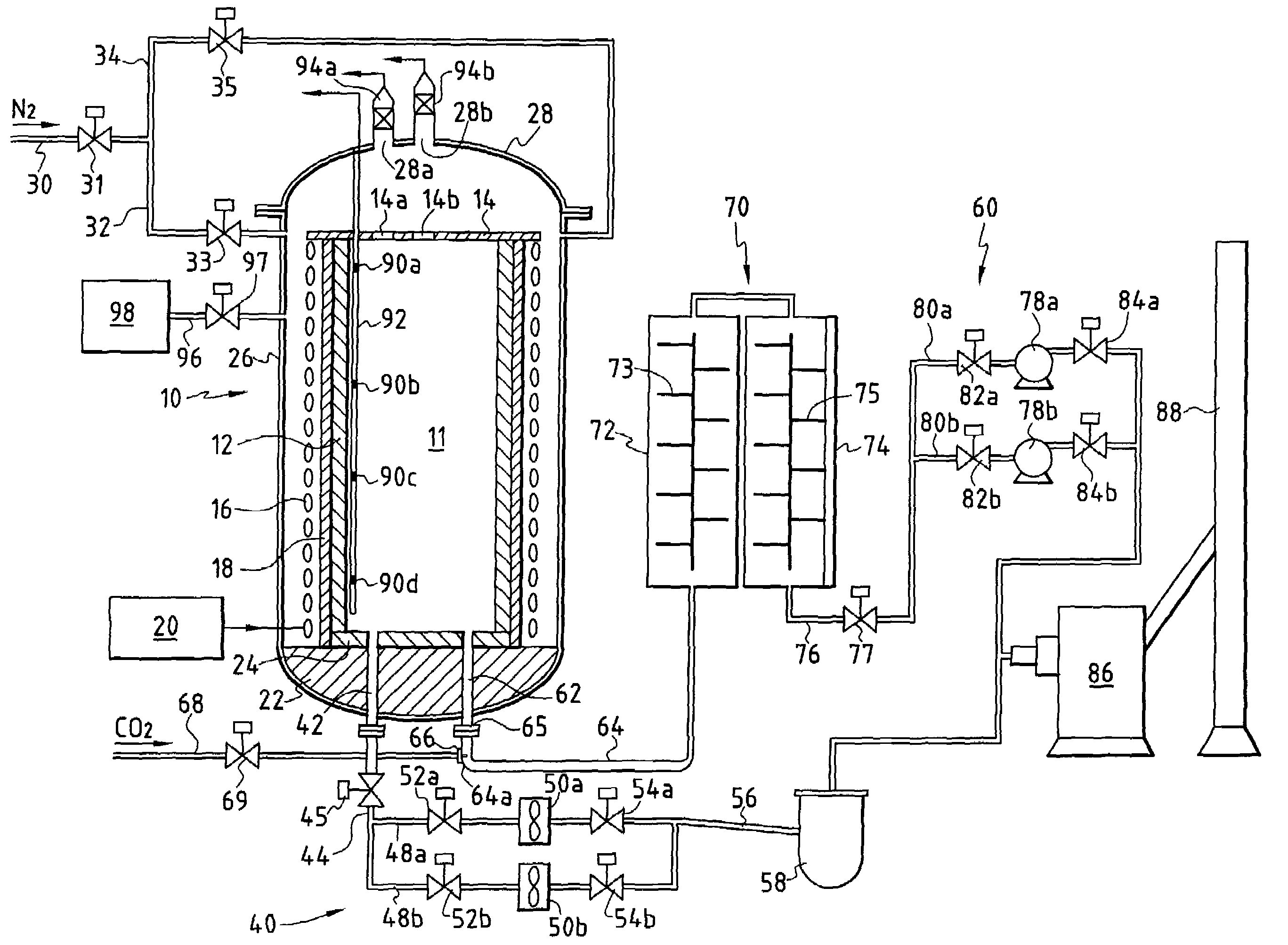
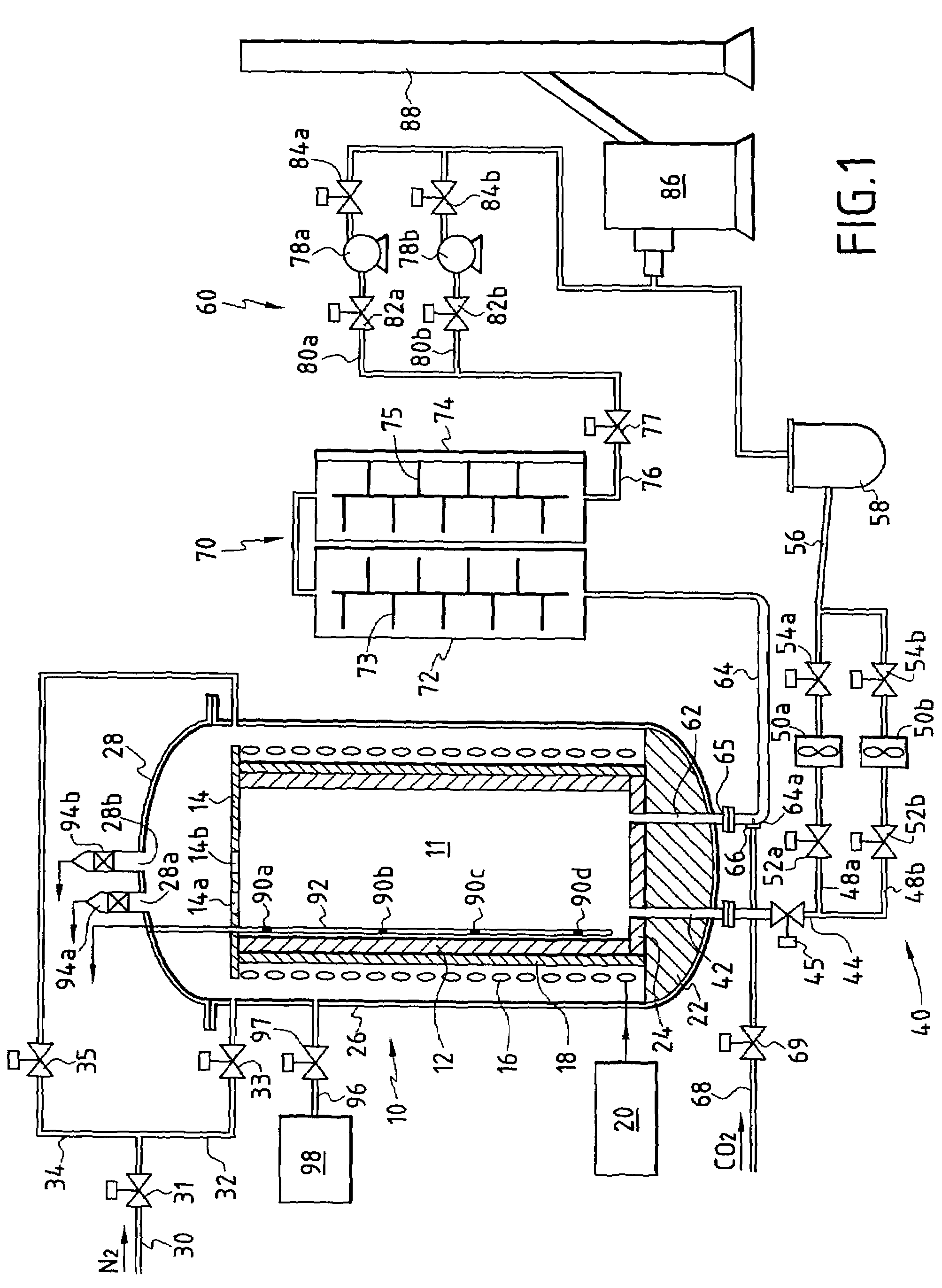
[0046]FIG. 1 is a highly diagrammatic representation of an oven 10 comprising a susceptor 12 in the form of a vertical axis cylinder defining the sides of a volume or enclosure 11 for filling with bodies (not shown) made of a carbon-precursor material, for example pieces of fabric made of preoxidized PAN fiber. The susceptor is surmounted by a cover 14.

[0047]The susceptor 12, which is made of graphite for example, is heated by inductive coupling with an induction coil 16 which surrounds the susceptor, with thermal insulation 18 being interposed between them. The induction coil is powered by a control circuit 20 which delivers electricity as a function of the heating requirements of the oven.

[0048]The induction coil can be subdivided into a plurality of sections along the vertical dimension of the oven. Each section is individually powered with electricity so as to define different heating zones within the oven, in which zones temperature can be regulated independently.

[0049]The bott...


PUM

PropertyMeasurementUnit
temperatureaaaaaaaaaa

Abstract

The method comprises a first stage of transforming carbon precursor material into carbon by heating, with the resulting gaseous effluent being extracted continuously, and a second stage of high temperature heat treatment under low pressure with the resulting gaseous effluent being extracted continuously. The first and second stages are performed one after the other in the same oven by proceeding, after the end of the first stage, with the steps of switching the gaseous effluent outlet from the oven to interrupt a connection with a first extractor device and to establish a connection with a second extractor device, of adjusting the pressure inside the oven to the value required for the second stage, and of adjusting the heating temperature of the oven starting from the temperature reached at the end of the first stage. It is also possible to switch temperature measurement from at least one first sensor to at least one second sensor different from the first. During the second stage, any alkali metal such as sodium contained in sublimed form in the gaseous effluent coming from the oven can be neutralized, e.g. by injecting CO2 into an effluent exhaust pipe.

Description

BACKGROUND OF THE INVENTION[0001]The invention relates to making carbon bodies from bodies made of carbon-precursor material.[0002]A particular field of application of the invention lies in making carbon fiber fabrics or preforms for use in constituting fiber reinforcement for parts made of thermostructural composite material such as carbon / carbon (C / C) composite and carbon-reinforced ceramic matrix composite. Such carbon fiber preforms are conventionally obtained from carbon-precursor fiber fabrics which are better at withstanding the textile operations required for shaping said fabrics than are carbon fibers.[0003]Amongst carbon precursors, in particular precursors in the form of fibers, preoxidized polyacrylonitrile (PAN) is commonly used. At least for certain uses, it is necessary not only to transform preoxidized PAN fiber fabric into carbon, but also to eliminate any metals or metallic impurities that come from the precursor, i.e. mainly sodium. That is why carbon bodies are u...

Claims


Application Information

Patent Timeline
Patent Type & Authority Patents(United States)
IPC IPC(8): D01F9/12C04B35/52C04B35/83
CPCC04B35/83C04B2235/72C04B2235/5268C04B35/52
Inventor LONCLE, JEAN-ETIENNEPOTHIER, PASCAL
Owner MESSIER BUGATTI INC
Why Eureka
Try Eureka