Blade-pitch-angle control device and wind power generator

a control device and blade-pitch angle technology, applied in the direction of rotors, marine propulsion, vessel construction, etc., can solve the problems of inability to quickly obtain instantaneous load, processing time, disadvantageous processing, etc., and achieve the effect of reducing acceleration, reducing acceleration, and reducing acceleration

a control device and blade-pitch angle technology, applied in the direction of rotors, marine propulsion, vessel construction, etc., can solve the problems of inability to quickly obtain instantaneous load, processing time, disadvantageous processing, etc., and achieve the effect of reducing acceleration, reducing acceleration, and reducing acceleration

US7452185B2Active Publication Date: 2008-11-18MITSUBISHI HEAVY IND LTD

Image

  • Blade-pitch-angle control device and wind power generator
  • Blade-pitch-angle control device and wind power generator
  • Blade-pitch-angle control device and wind power generator

Examples


first embodiment

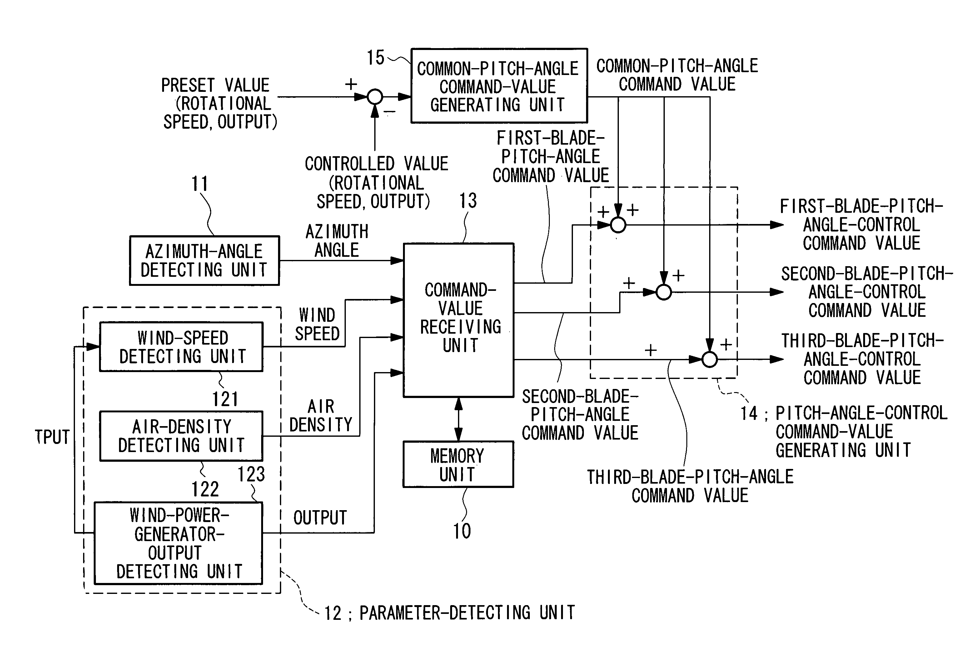
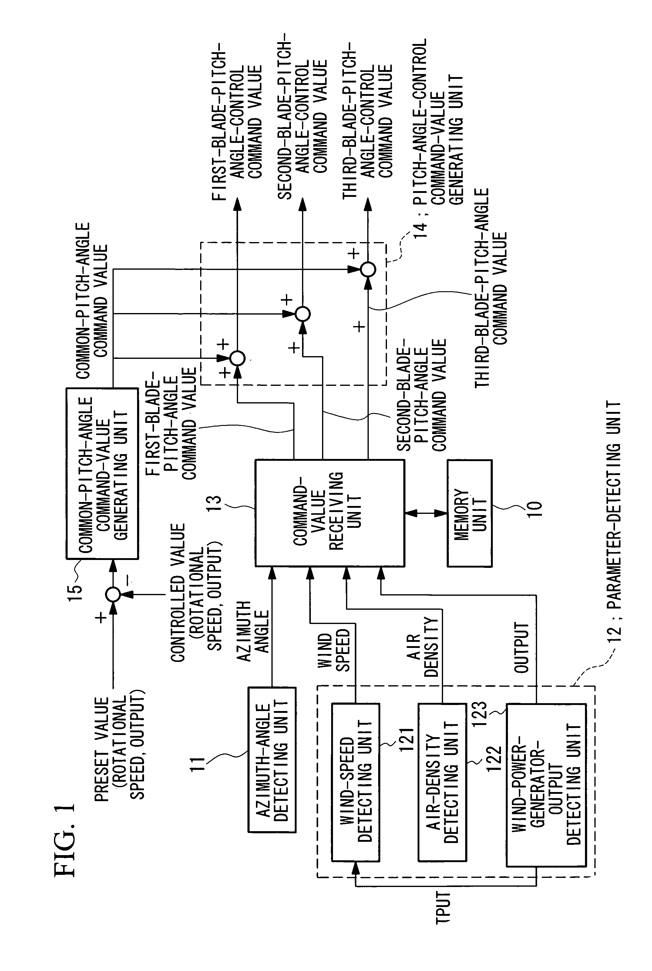
[0074]FIG. 1 is a block diagram showing the structure of a blade-pitch-angle control device that is applied to a wind power generator using a constant-speed windmill.

[0075]As shown in FIG. 1, the blade-pitch-angle control device according to this embodiment includes a memory unit (memory device) 10, an azimuth-angle detecting unit (azimuth-angle detecting device) 11, a parameter-detecting unit (parameter-detecting device) 12, a command-value receiving unit (command-value receiving device) 13, a pitch-angle-control command-value generating unit (pitch-angle-control command-value generating device) 14, and a common-pitch-angle command-value generating unit (common-pitch-angle command-value generating device) 15.

[0076]In the memory unit 10, predetermined parameters that affect the load fluctuation of blades, for example, wind speed, temperature, and output of the wind power generator; azimuth angles; and pitch-angle command values are stored in association with each other.

[0077]As show...

second embodiment

[0138]A blade-pitch-angle control device according to a second embodiment of the present invention will now be described.

[0139]FIG. 10 is a block diagram showing the structure of a blade-pitch-angle control device that is applied to a wind power generator used in a variable-speed windmill.

[0140]As shown in FIG. 10, the blade-pitch-angle control device according to the present embodiment includes load-measuring units (load-measuring devices) 30, a frequency analysis unit (calculation device) 31, an adjusting pitch-angle generating unit (adjusting pitch-angle command-value generating device) 32, a pitch-angle-control command-value generating unit (pitch-angle-control command-value generating device) 36, and a common-pitch-angle command-value generating unit 15.

[0141]Each of the load-measuring units 30 measures a load applied to a corresponding blade at predetermined azimuth angles (for example, every 6°), and outputs the measurement results as an electrical signal.

[0142]The load-measu...


PUM


Abstract

A blade-pitch-angle control device includes a memory unit in which predetermined parameters that affect the load fluctuation of blades, azimuth angles, and pitch-angle command values are stored in association with each other; an azimuth-angle detecting unit that detects the azimuth angle of each of the blades; a parameter-detecting unit that detects the predetermined parameters; a command-value receiving unit that receives pitch-angle command values for each of the blades from the memory unit, the pitch-angle command values being selected on the basis of the azimuth angle of each blade detected by the azimuth-angle detecting unit and the predetermined parameters detected by the parameter-detecting unit; and a pitch-angle-control command-value generating unit that generates pitch-angle-control command values for individually controlling the pitch-angle of each blade on the basis of the pitch-angle command values and a common-pitch-angle command value.

Description

CROSS-REFERENCE TO RELATED APPLICATIONS[0001]The present application is based on International Application No. PCT / JP / 2004 / 013144 filed on Sep. 9, 2004, which in turn corresponds to Japanese Application Number 2003-318312 filed Sep. 10, 2003 and Japanese Application Number 2004-143642 filed May 13, 2004, and priority is hereby claimed under 35 USC § 119 based on these applications. Each of these applications are hereby incorporated by reference in their entirety into the present application.TECHNICAL FIELD[0002]The present invention relates to a wind power generator, and in particular, to a blade-pitch-angle control device for controlling a blade-pitch-angle of a windmill.BACKGROUND ART[0003]As shown in a schematic view in FIG. 11, a known propeller windmill used in wind power generators includes, for example, three blades composed of a first blade 1, a second blade 2, and a third blade 3, a rotor 5 serving as a link mechanism for linking the three blades, a tower 4, and so on.[0004...

Claims


Application Information

Patent Timeline
18 Nov 2008
Publication
US7452185B2
IPC
F03D7/04; F03D7/02
CPC
F03D7/0224; F03D7/024; F03D7/043; Y02E10/723; F05B2270/326; F05B2270/331; F05B2270/335; F05B2270/32
Inventors
IDE, KAZUNARI; HAYASHI, YOSHIYUKI