Cyclone dust separating apparatus for vacuum cleaner and vacuum cleaner having the same

a technology vacuum cleaner, which is applied in the direction of vortex flow apparatus, filtration separation, separation process, etc., can solve the problems of limited cleaning operation of poor cleaning effect of conventional cyclone dust separation apparatus, and inability to separate dust separating devices. to achieve the effect of improving the efficiency of contaminant separation

Active Publication Date: 2008-12-09
SAMSUNG GWANGJU ELECTRONICS CO LTD
View PDF29 Cites 41 Cited by
  • Summary
  • Abstract
  • Description
  • Claims
  • Application Information

AI Technical Summary

Benefits of technology

[0008]Accordingly, the present general inventive concept has been made to solve the above-mentioned and / or problems, and an aspect of the present general inventive concept is to provide a cyclone dust separating apparatus that is compact-sized and yet provides improved contaminant separation efficiency and a vacuum cleaner having such a cyclone dust separating apparatus.
[0010]Accordingly, the multi-stage cyclone dust separating apparatus can improve cleaning efficiency while remaining compact-sized.
[0014]The first to third cyclone chambers may be formed independently from each other. As the air flowing into the respective cyclone chambers is provided with spaces for whirling current, the contaminant separation efficiency can be far more improved in comparison with the structure where the cyclone chambers are superimposed.
[0016]The second cover may include a first curvature part and a second curvature part formed by curving a part of the second cover, forming the first passage when the cyclone body is connected with the second cover; and a hollow connecting pipe extended toward the upper side of the second cover, connecting the outlets of the second cyclone chambers with the third chamber. The first through third passages can be formed at one time by connecting the second cover with the cyclone body. Even when a plurality of cyclone chambers is formed, it is possible to prevent the complexity of the structure for the air flow.

Problems solved by technology

Accordingly, in the conventional cases, a cyclone dust separating devices can only separate the contaminants that are large enough to be handled by the structure of the cyclone chamber.
Such a limited cleaning operation of the cyclone dust separating apparatus is disadvantageous especially for the cyclone dust separating apparatuses for vacuum cleaners, that are required to separate almost every contaminants regardless of particle sizes.
The conventional cyclone dust separating apparatus is particularly poor at cleaning fine contaminants, and in order to solve this problem, studies have recently carried out to develop a cyclone dust separating apparatus that has a plurality of cyclone chambers and separate contaminants in multiple stages.
The problem of this approach is that, as the number of cyclone chambers increases to satisfy the desired contaminant separation efficiency, the overall size of the cyclone dust separating apparatus is enlarged and structure is complicated, which is obviously not beneficial to use in the vacuum cleaner.

Method used


Image

  • Cyclone dust separating apparatus for vacuum cleaner and vacuum cleaner having the same
  • Cyclone dust separating apparatus for vacuum cleaner and vacuum cleaner having the same
  • Cyclone dust separating apparatus for vacuum cleaner and vacuum cleaner having the same

Examples


Embodiment Construction

[0025]Certain embodiments of the present invention will be described in greater detail with reference to the accompanying drawings.

[0026]In the following description, same drawing reference numerals are used for the same elements even in different drawings. The matters defined in the description such as a detailed construction and elements are nothing but the ones provided to assist in a comprehensive understanding of the invention. Thus, it is apparent that the present invention can be carried out without those defined matters. Also, well-known functions or constructions are not described in detail since they would obscure the invention in unnecessary detail.

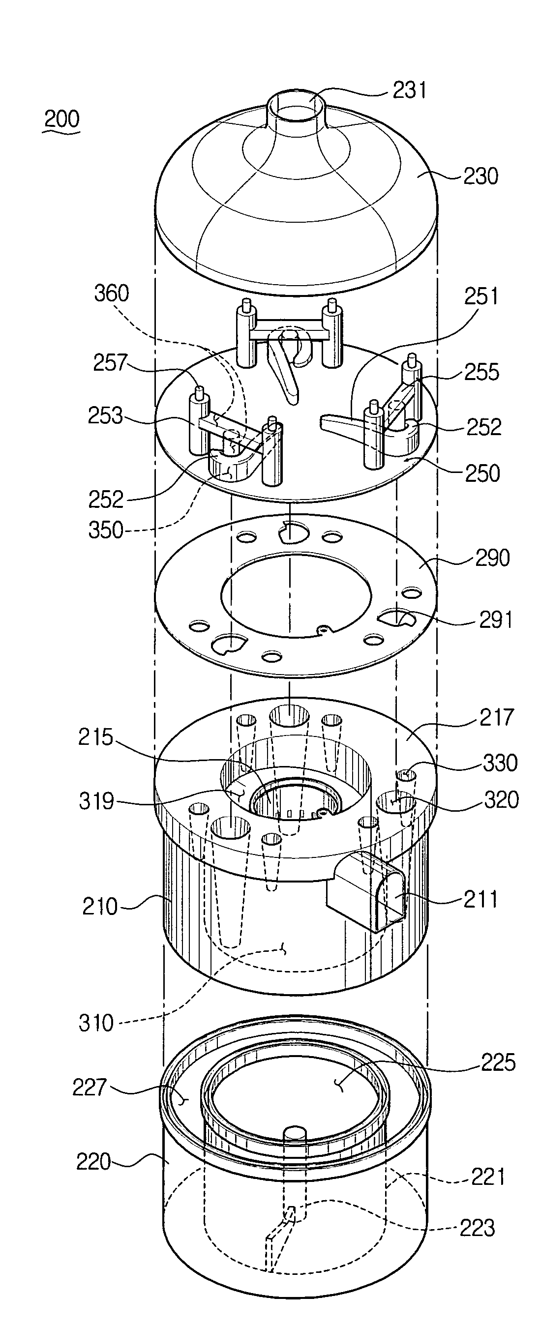
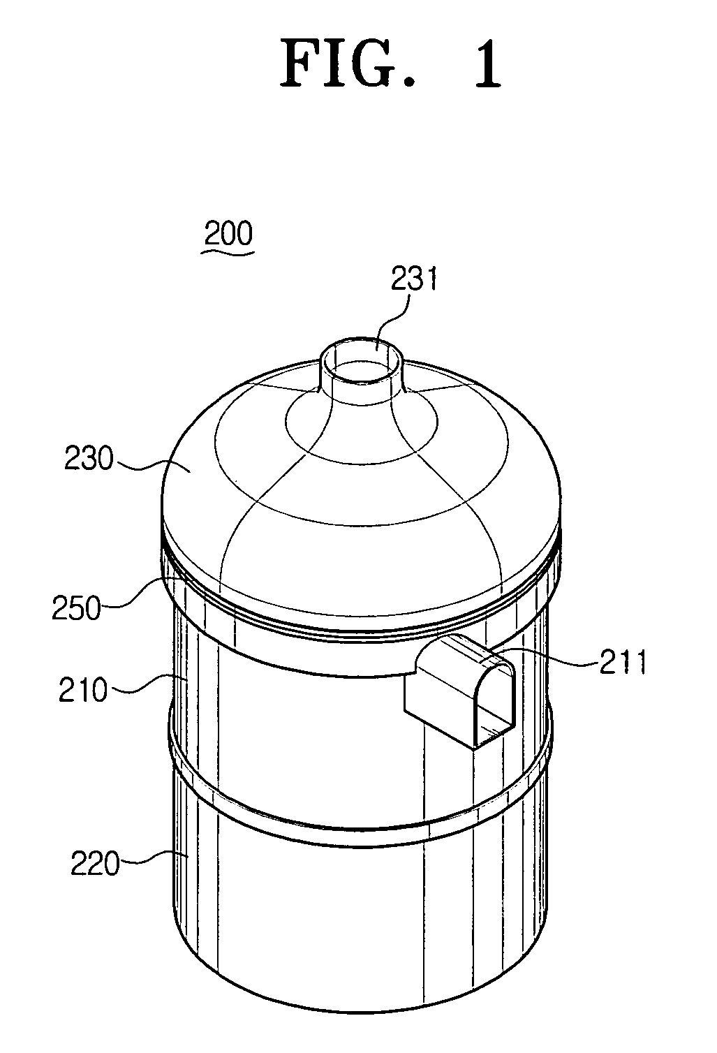
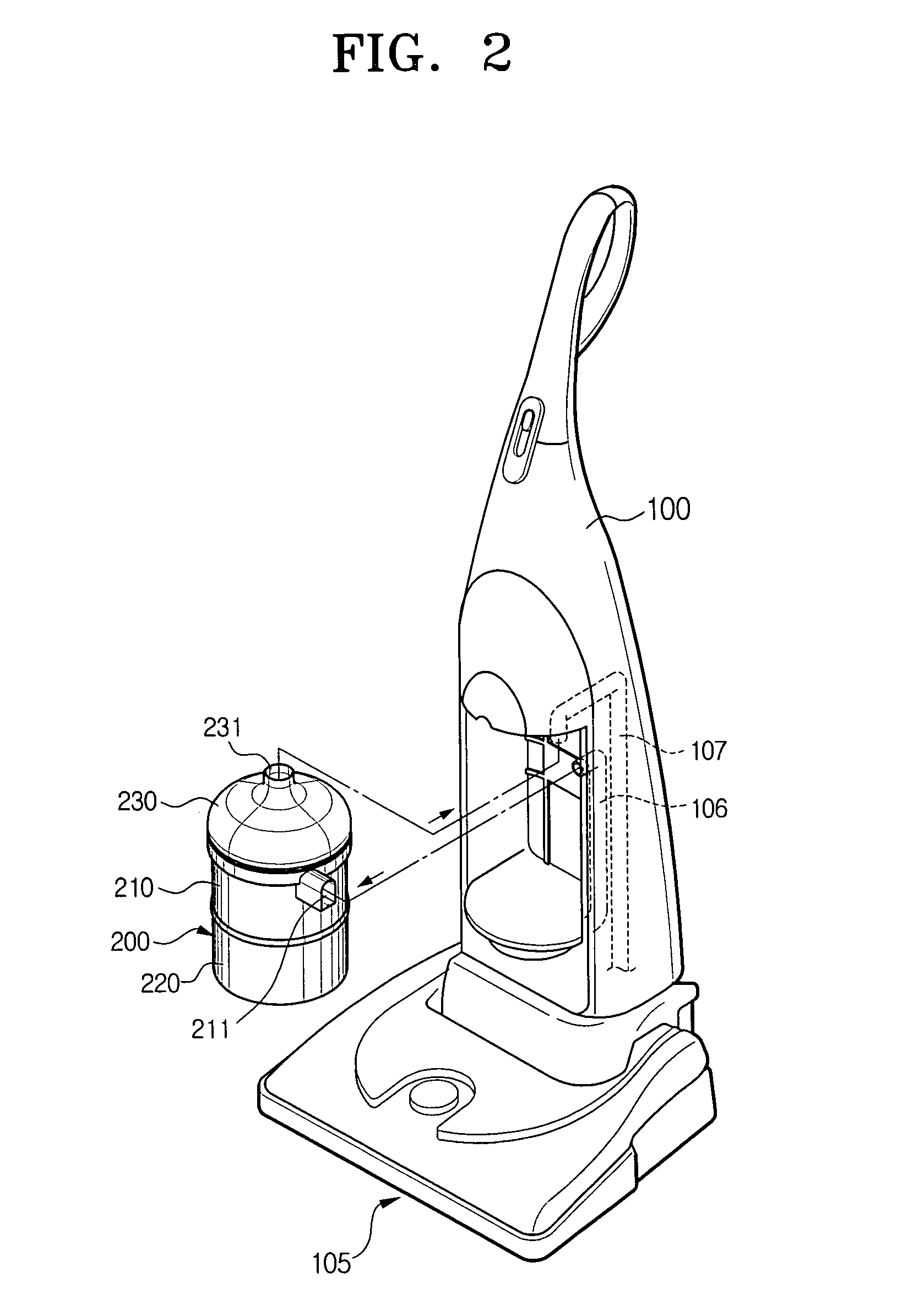
[0027]Referring to FIGS. 1 and 2, a cyclone dust separating apparatus 200 according to an exemplary embodiment of the present invention is mounted in a vacuum cleaner 100. Cyclone dust separating apparatus 200 includes an inlet 211 and an outlet 231, which are connected to an air suction pie 106 and an air discharge pipe 107 of...


PUM

PropertyMeasurementUnit
centrifugal forceaaaaaaaaaa
inner diameteraaaaaaaaaa
suction forceaaaaaaaaaa

Abstract

A cyclone dust separating apparatus has a first cyclone chamber for separating particles from the externally-drawn fluid by centrifugal force, one or more second cyclone chambers for separating particles from the fluid discharged from the first cyclone chamber by centrifugal force, and one or more third cyclone chambers for separating particles from the fluid discharged from the second cyclone chambers, and causing the fluid to be discharged out via a discharge passage. The second and the third cyclone chambers are arranged in radial relation with respect to the first cyclone chamber, and thus, surround the first cyclone chamber. Therefore, the cyclone dust separating apparatus provides multi-stage centrifugal cleaning process and improved cleaning efficiency, while remaining compact-sized.

Description

CROSS-REFERENCE TO RELATED APPLICATIONS[0001]This application claims the benefit of U.S. provisional application No. 60 / 665,941, filed Mar. 29, 2005, in the United States Patent and Trademark Office, and claims the benefit of Korean Patent Application No. 2005-38738, filed May 10, 2005, in the Korean Intellectual Property Office, the disclosures of both of which are incorporated herein by reference.BACKGROUND OF THE INVENTION[0002]1. Field of the Invention[0003]The present invention relates to a vacuum cleaner. More particularly, the present invention relates to a cyclone dust separating apparatus for separating contaminants from drawn air, and a vacuum cleaner having the same.[0004]2. Description of the Related Art[0005]Generally, a cyclone dust separating apparatus spins externally-drawn air or fluid therein and, thus, separates contaminants from the drawn-in fluid by using the centrifugal force generated from the spinning fluid. In other words, the cyclone dust separating apparat...

Claims


Application Information

Patent Timeline
Patent Type & Authority Patents(United States)
IPC IPC(8): B01D45/12
CPCA47L9/1625A47L9/1641A47L9/1683B01D45/14B04C5/24B04C5/26Y10S55/03A47L9/16A47L9/10
Inventor HAN, JUNG-GYUNOH, JANG-KEUNKIM, MIN-HA
Owner SAMSUNG GWANGJU ELECTRONICS CO LTD
Why Eureka
Try Eureka