Small form factor, field-installable optical fiber connector

a technology of optical fiber connector and installation plate, which is applied in the field of optical fiber connector, can solve the problems of complex structure, difficult rework of terminating fiber, and disclosure of clamping assembly, and achieve the effect of simple structure and convenient us

Active Publication Date: 2009-04-07
PROTAI PHOTONIC +1
View PDF8 Cites 102 Cited by
  • Summary
  • Abstract
  • Description
  • Claims
  • Application Information

AI Technical Summary

Benefits of technology

[0012]In order to achieve the foregoing object, the present invention provides an optical fiber connector including a connector housing, a ferrule and a clamping assembly. The connector hosing has a front end and a rear end. The ferrule is disposed in the connector housing and projects from the front end of the connector housing. The clamping assembly is disposed in the connector housing for mounting the ferrule, and includes a hollow housing and a cam member, wherein the cam member includes a groove adapted to clamp a terminating fiber when a cam effect between the hollow housing and the cam member is generated and further the cam effect causes the groove of the cam member to generate a clamping force.
[0013]According to the optical fiber connector of the present invention, it is easy to rework for the terminating fiber disclosed in the present invention. Once the installation of the terminating fiber is wrong, the terminating fiber can be pulled out from the optical fiber connector by a hand with / without a tool. Compared with the prior art, the clamping assembly of the present invention is a simple structure and is easily used.

Problems solved by technology

A conventional small form factor, optical fiber connector must be readily assembled in the factory, and there are too many separated components so as to have a complex processes of assembly.
However, it is difficult to rework for the terminating fiber disclosed in U.S. Patent Publication Number 2006 / 0002662 A1.
Furthermore, the clamping assembly disclosed by U.S. Patent Publication Number 2006 / 0002662 A1 is a complex structure.

Method used


Image

  • Small form factor, field-installable optical fiber connector
  • Small form factor, field-installable optical fiber connector
  • Small form factor, field-installable optical fiber connector

Examples


Embodiment Construction

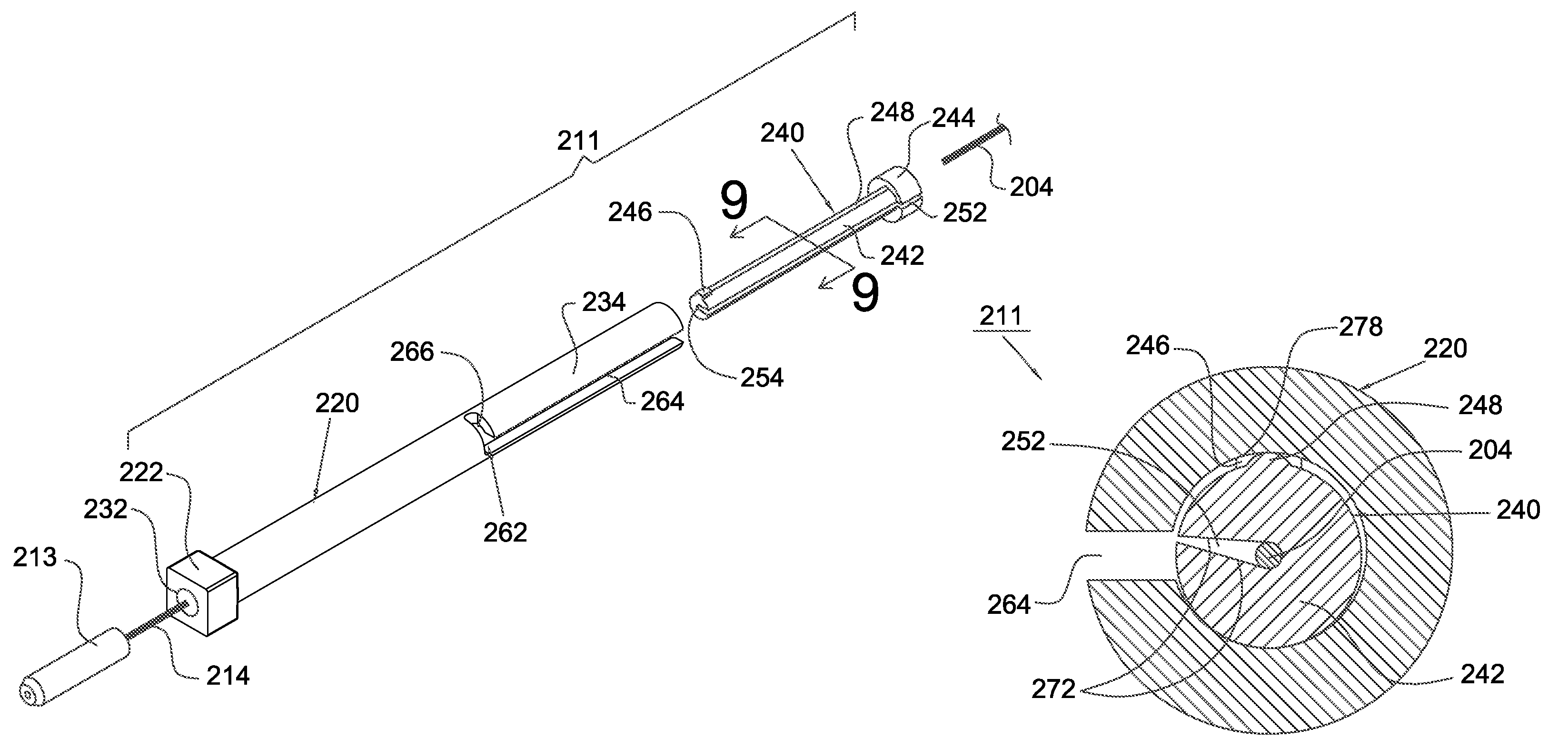
[0028]Referring to FIGS. 4 to 6, they depict an optical fiber connector 210 according to an embodiment of the present invention. The optical fiber connector 210 can be a kind of small form factor, field-installable optical fiber connector, or a kind of small form factor, factory-installable optical fiber connector. In this embodiment, the optical fiber connector 210 which is the small form factor, field-installable optical fiber connector is discussed in greater detail below.

[0029]The optical fiber connector 210 includes a connector housing 212, a ferrule 213, a clamping assembly 211, a resilient member 215 and an insert member 216. The connector housing 212 can be a small form factor housing and defines a front orientation 206 and a back orientation 208. The ferrule 213 is disposed in the connector housing 212 and projects from a front end 274 of the connector housing 212 along the front orientation 206. A fiber stub 214 is already terminated, polished in a ferrule 213, and mounted...


PUM


Abstract

An optical fiber connector includes a connector housing, a ferrule and a clamping assembly. The connector hosing has a front end and a rear end. The ferrule is disposed in the connector housing and projects from the front end of the connector housing. The clamping assembly is disposed in the connector housing for mounting the ferrule, and includes a hollow housing and a cam member, wherein the cam member includes a groove adapted to clamp a terminating fiber when a cam effect between the hollow housing and the cam member is generated and further the cam effect causes the groove of the cam member to generate a clamping force.

Description

BACKGROUND OF THE INVENTION[0001]1. Field of the Invention[0002]The present invention generally relates to an optical fiber connector, and more particularly to an optical fiber connector including a clamping assembly having a groove of a cam member, which can generate a clamping force and be adapted to clamp a terminating fiber.[0003]2. Description of the Related Art[0004]Recently, optical fibers have been widely used as signal transmission media because of their high bandwidth and low loss nature. In order to transmit over a longer distance, it is common to use a high power diode laser to launch a laser beam into the optical fiber. An optical fiber connector is a mechanical device disposed at an end of the optical fiber and acts as a connector of optical path when the optical fibers are joined to each other.[0005]A conventional small form factor, optical fiber connector must be readily assembled in the factory, and there are too many separated components so as to have a complex pro...

Claims


Application Information

Patent Timeline
Patent Type & Authority Patents(United States)
IPC IPC(8): G02B6/36
CPCG02B6/3846G02B6/3858
Inventor LIN, I ENMAMIYA, TOMOYUKI
Owner PROTAI PHOTONIC
Why Eureka
Try Eureka