Dental fixture implantation system and associated method

a technology of dental implants and fixed brackets, applied in the field of dental implants, can solve the problem of insufficient bone in which to implant a dental implant fixture in the alveolar ridge, and achieve the effect of increasing stability

Inactive Publication Date: 2009-05-12
CLEMENT MILTON A
View PDF73 Cites 12 Cited by
  • Summary
  • Abstract
  • Description
  • Claims
  • Application Information

AI Technical Summary

Benefits of technology

[0010]The upper portion, lower portion, and intermediate offset-defining portion of the dental implant fixture may be integrally formed as a monolithic unit. In addition, a cross-member may be carried by the intermediate offset-defining portion and / or the bottom portion for increased stability. The dental prosthesis may be connected to the upper portion of the dental implant fixture.

Problems solved by technology

Another frequently observed problem related to the implantation of a dental prosthesis is that when a prosthesis is needed by a patient, it usually is needed where the patient has also experienced bone loss or deterioration in the alveolar ridge.
When, as a result of disease or injury, bone loss has occurred in or around where a dental prosthesis is needed, it may be that there is not enough bone in which to implant a dental implant fixture in the alveolar ridge.
Unfortunately, such conventional techniques and dental fixtures require a patient to make multiple visits to the attending physician and / or may require a lengthy interval between the initial operation and the final installation of the dental prosthesis.

Method used


Image

  • Dental fixture implantation system and associated method
  • Dental fixture implantation system and associated method
  • Dental fixture implantation system and associated method

Examples


Embodiment Construction

[0019]The invention will now be described more fully hereinafter with reference to the accompanying drawings, in which preferred embodiments of the invention are shown. This invention may, however, be embodied in many different forms and should not be construed as limited to the embodiments set forth herein. Rather, these embodiments are provided so that this disclosure will be thorough and complete, and will fully convey the scope of the invention to those skilled in the art. Like numbers refer to like elements throughout, and prime notation is used to indicate similar elements in alternative embodiments.

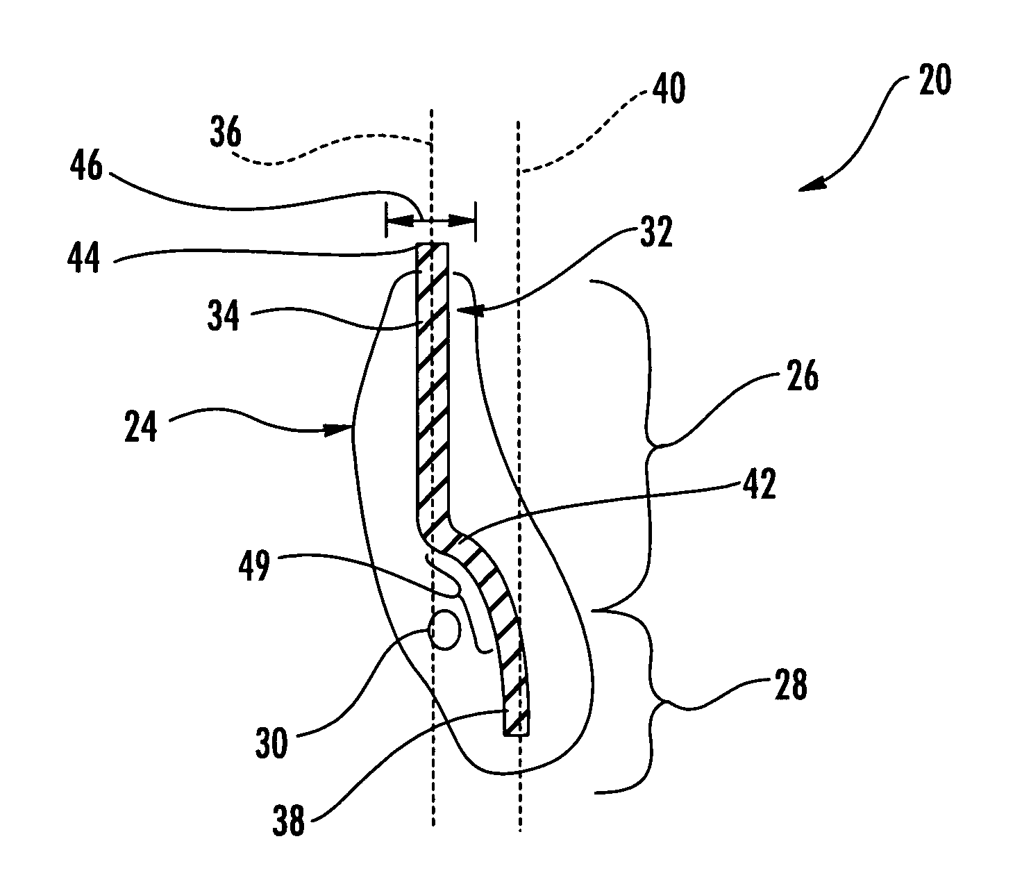
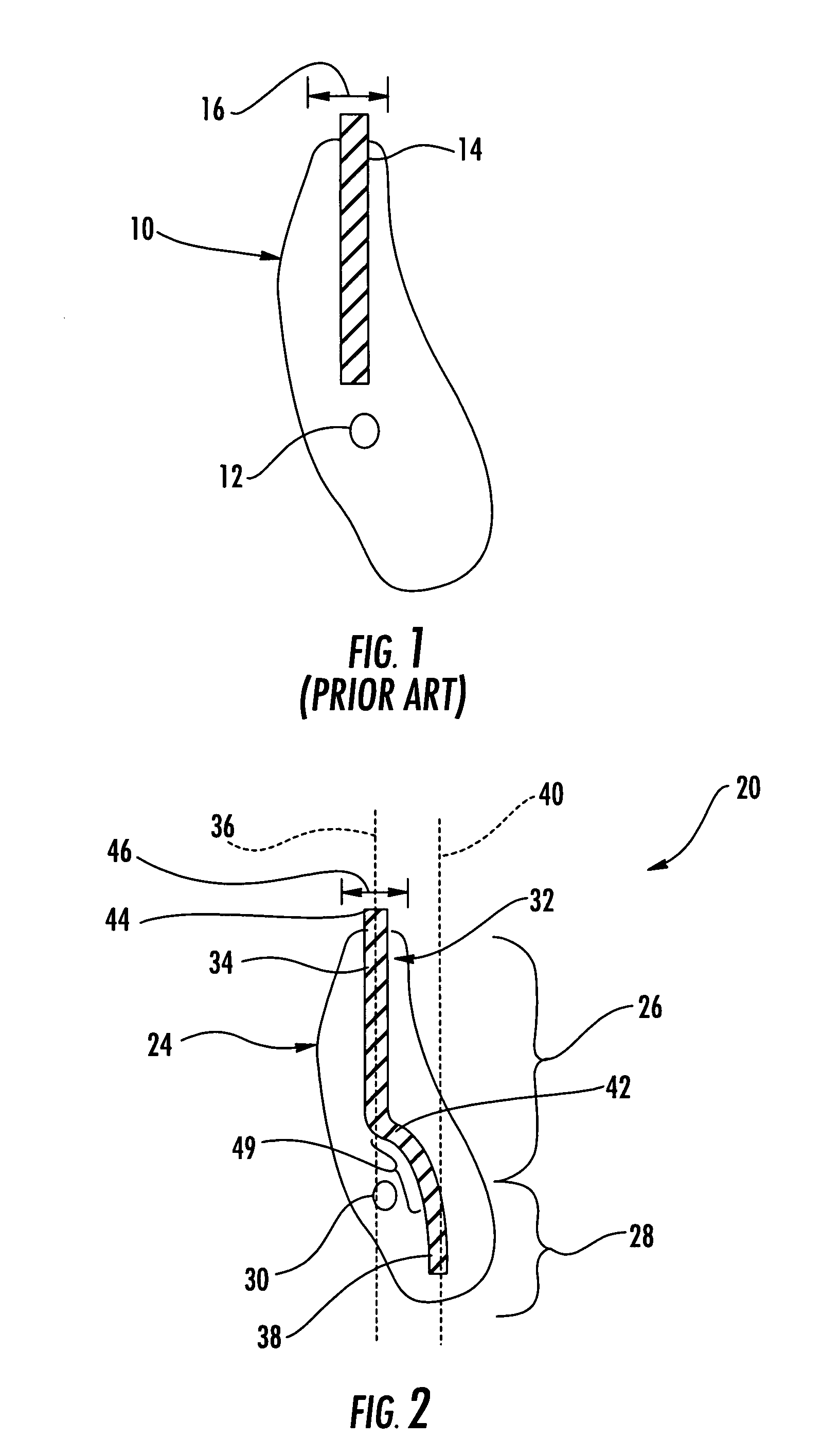
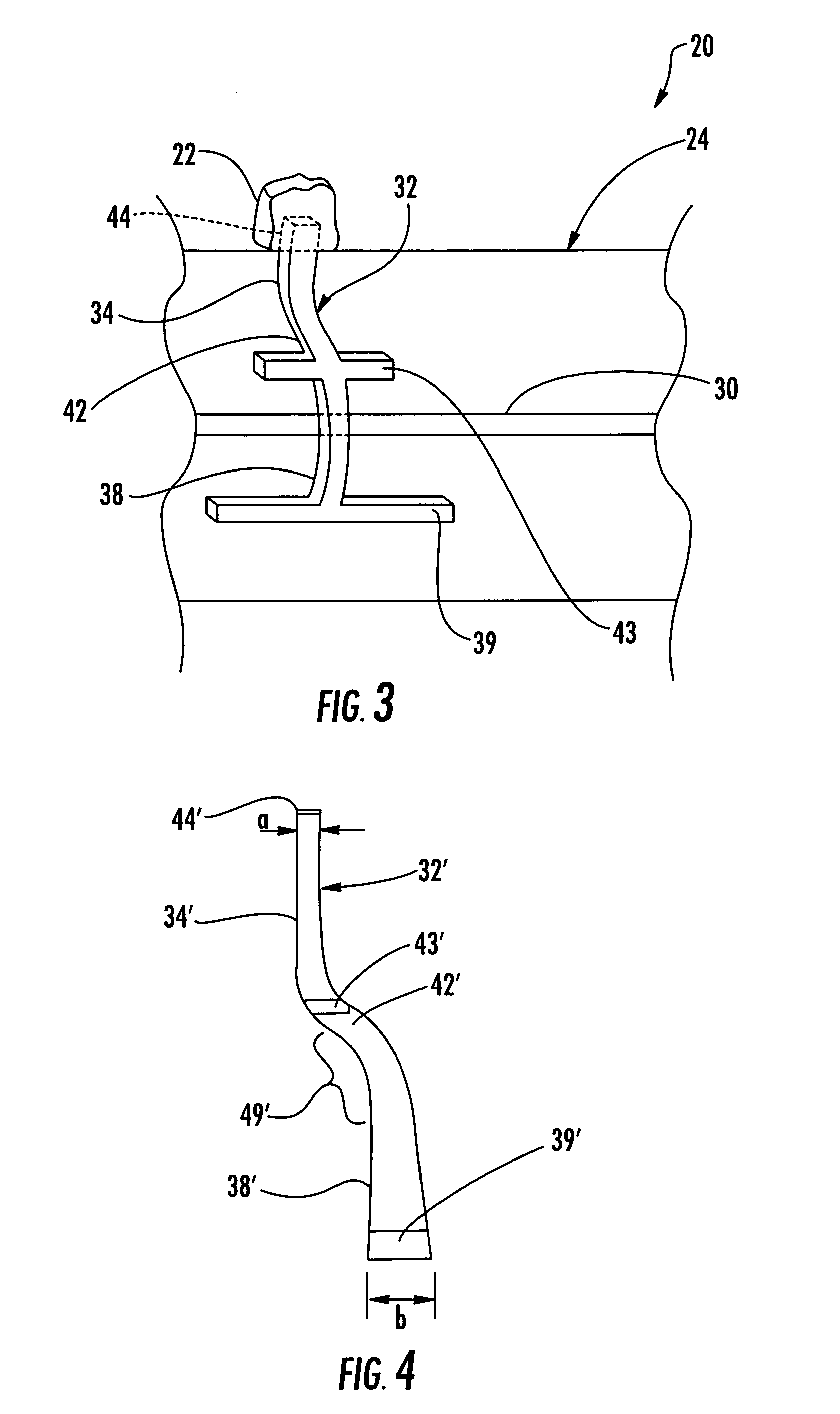
[0020]Referring initially to FIGS. 2 and 3, a dental implantation system 20 for securing a dental prosthesis 22 in a patient's jawbone 24 is described. The patient's jawbone 24 includes an alveolar bone 26, a basal bone 28 adjacent the alveolar bone, and a neurovascular bundle 30 running through the jawbone.

[0021]The dental implantation system 20 includes a dental implant fixture 3...


PUM


Abstract

A dental implantation system is for securing a dental prosthesis in a patient's jawbone including an alveolar bone, a basal bone adjacent the alveolar bone, and a neurovascular bundle running through the jawbone. The dental implantation system may include a dental implant fixture having an elongate shape and including an upper portion to be positioned in the alveolar bone to receive the dental prosthesis and defining a first axis. The dental implant fixture may also include a lower portion to be positioned in the basal bone and defining a second axis. The dental implant fixture may further include an intermediate offset-defining portion between the upper portion and the lower portion to define an offset between the first axis and the second axis so that the lower portion avoids the neurovascular bundle.

Description

FIELD OF THE INVENTION[0001]The invention relates to the field of dentistry, and, more particularly, to dental implants and related methods.BACKGROUND OF THE INVENTION[0002]A dental implant can be surgically implanted in a dental patient and a prosthesis mounted on the implant to replace a natural tooth that the patient has lost due to decay or injury. Such a dental prosthesis can be an artificial tooth or crown that affixes to a post that is secured to the patient's alveolar ridge, the bone ridge that forms the borders of the upper and lower jaws and contains the sockets of the patient's teeth.[0003]Some of the problems with prior art dental implant fixtures are explained with reference to FIG. 1. A patient's jawbone 10 includes a neurovascular bundle 12 or a sinus that limits the depth at which a dental implant fixture 14 can be positioned into the jawbone thereby limiting the anchor strength of the dental implant fixture. Another frequently observed problem related to the implant...

Claims


Application Information

Patent Timeline
Patent Type & Authority Patents(United States)
IPC IPC(8): A61C13/08A61C8/00A61F2/28
CPCA61C8/0027
Inventor CLEMENT, MILTON A.
Owner CLEMENT MILTON A
Why Eureka
Try Eureka