Slide-type portable terminal using flexible material

a portable terminal and flexible material technology, applied in the direction of connection contact material, substation equipment, coupling device connection, etc., can solve the problems of increased manufacturing cost, reduced assembly convenience and productivity, and generated slide-type portable terminals, and achieve low manufacturing cost and simple structure

a portable terminal and flexible material technology, applied in the direction of connection contact material, substation equipment, coupling device connection, etc., can solve the problems of increased manufacturing cost, reduced assembly convenience and productivity, and generated slide-type portable terminals, and achieve low manufacturing cost and simple structure

US7532916B2Inactive Publication Date: 2009-05-12SAMSUNG ELECTRONICS CO LTD

Image

  • Slide-type portable terminal using flexible material
  • Slide-type portable terminal using flexible material
  • Slide-type portable terminal using flexible material

Examples


Embodiment Construction

[0031]Hereinafter, a preferred embodiment of the present invention will be described with reference to the accompanying drawings. In the following description of the present invention, a detailed description of known functions and configurations incorporated herein is omitted to avoid making the subject matter of the present invention unclear.

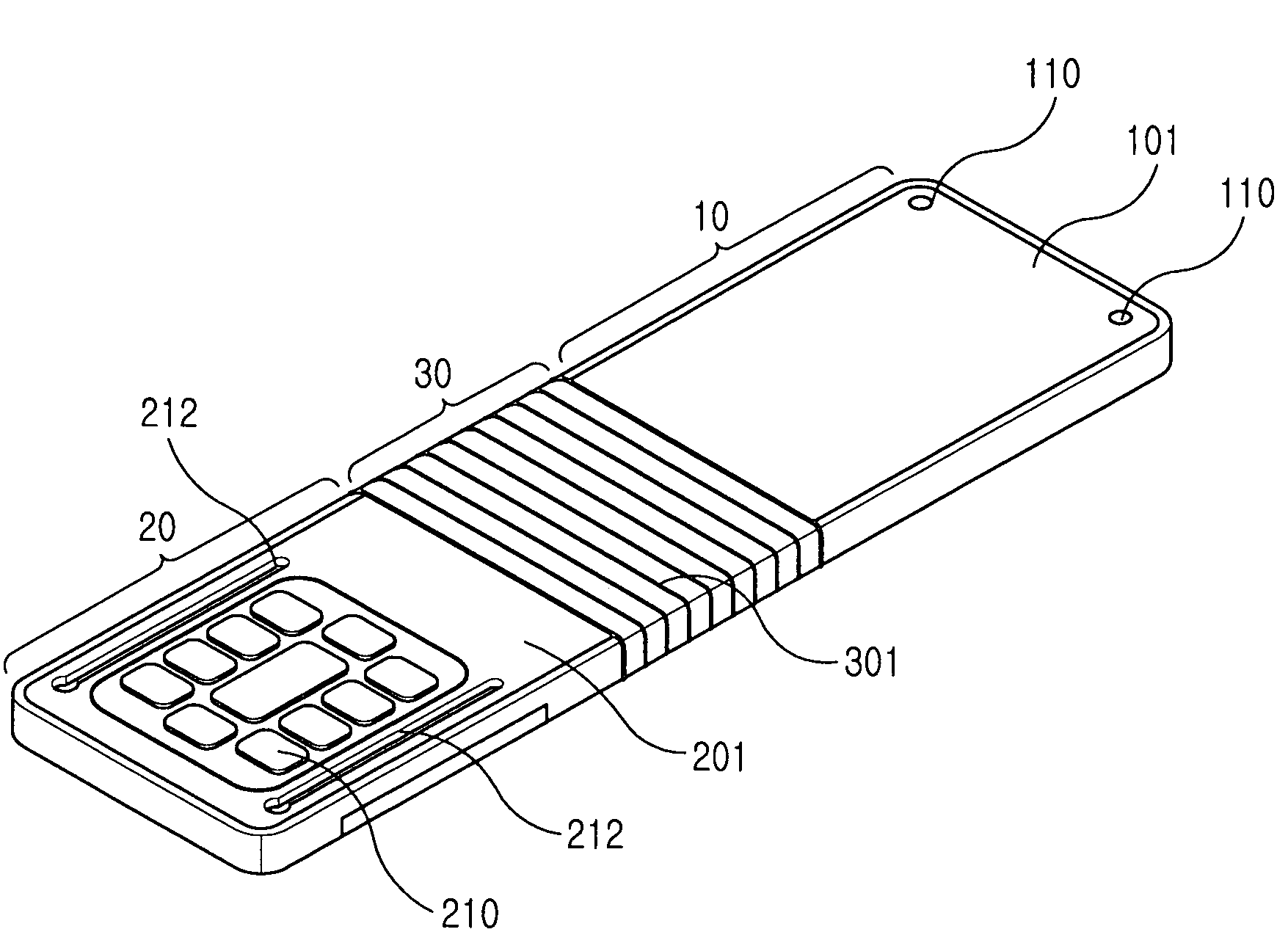
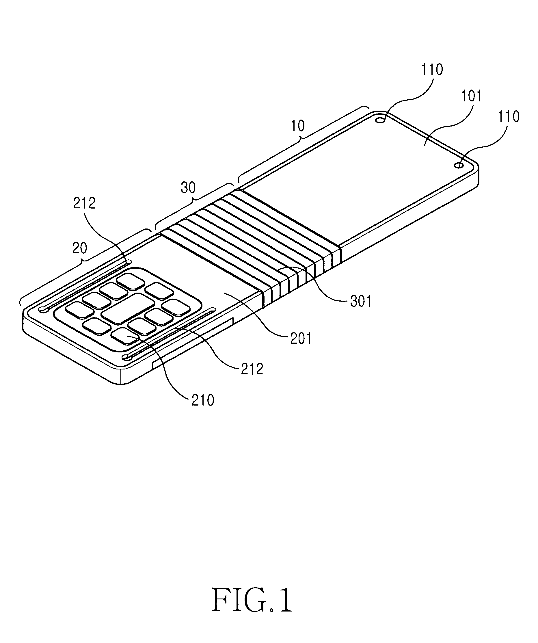
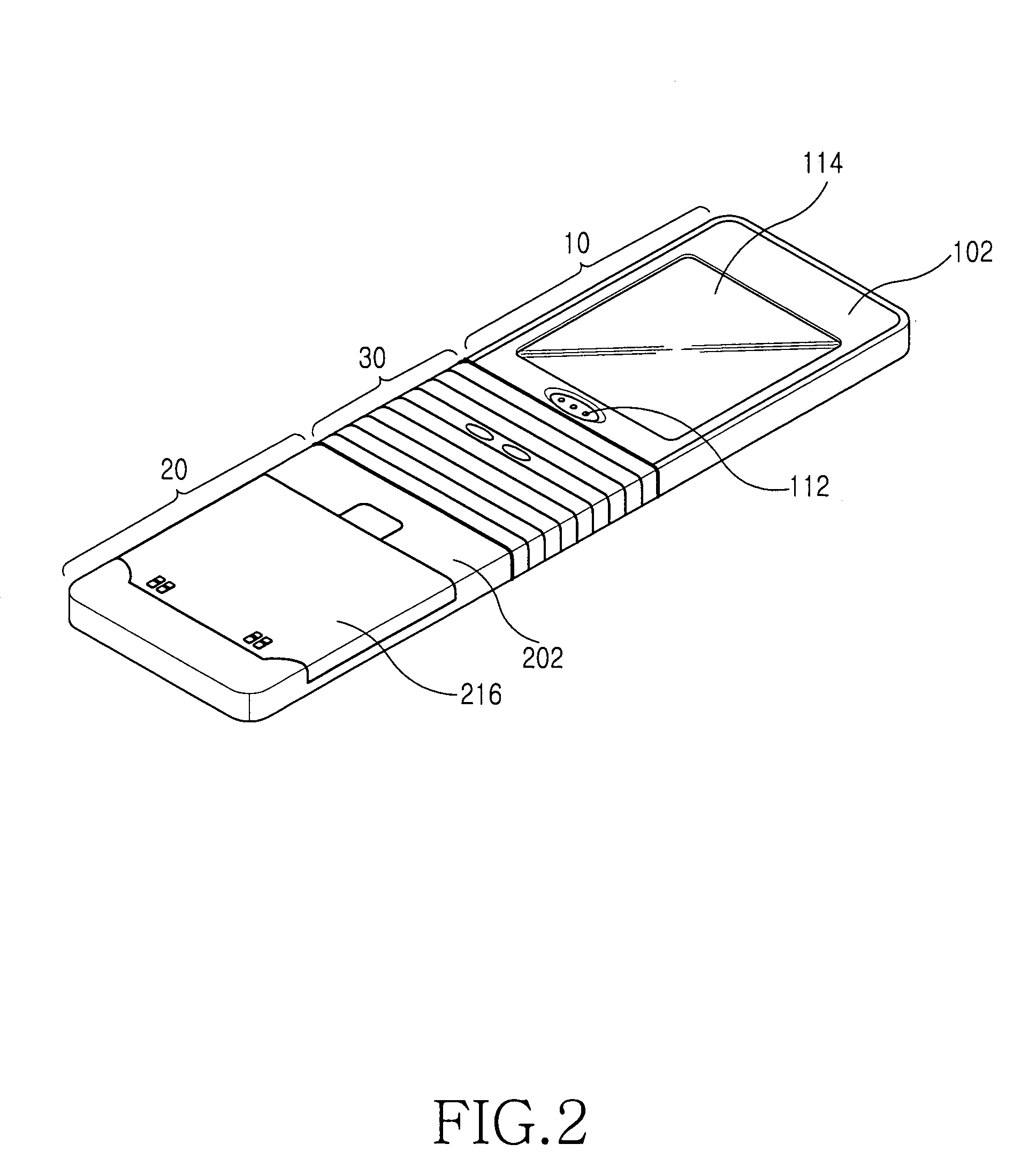
[0032]As shown in FIGS. 1 and 2, a portable terminal according to the present invention includes an upper portion 10, a lower portion 20 and a flexible portion 30 integrally connecting the upper portion 10 and the lower portion 20. The upper and lower portions 10 and 20 are linearly connected to each other by the flexible portion 30. This state is shown in FIGS. 1 and 2. since the flexible portion 30 includes a plurality of wrinkle portions 301 and can be bent or folded, the upper portion 10 can be bent or folded about the flexible portion 30 and can be slid on the lower portion 20 in the lengthwise direction of the lower portion 20. The wrinkl...


PUM


Abstract

Disclosed is a portable terminal using a flexible material. The portable terminal includes an upper portion, a lower portion and a flexible portion integrally connecting the upper and lower portions. The portable terminal is of a slide-type in which after the upper portion is bent about the flexible portion, the upper portion is slid in the lengthwise direction of the lower portion to open / close a predetermined area of the lower portion.

Description

PRIORITY[0001]This application claims priority to an application entitled “SLIDE-TYPE PORTABLE TERMINAL USING FLEXIBLE MATERIAL” filed with the Korean Intellectual Property Office on Aug. 5, 2005 and assigned Serial No. 2005-71970, the contents of which are incorporated herein by reference.BACKGROUND OF THE INVENTION[0002]1. Field of the Invention[0003]The present invention relates to a DMB (Digital Media Broadcast) phone, a game phone, a chatting phone, a camera phone, an MP3 phone, a cellular phone, a PCS (Personal Communications Service), a PDA (Personal Digital Assistants), an HHP (Hand Held Phone), and the like, and more particularly to a slide-type portable terminal using a flexible material.[0004]2. Description of the Related Art[0005]In general, a “portable terminal” refers to an electronic device that a user can carry to perform wireless communication with a desired partner. To facilitate portability, designs of such portable terminals tend not only to be compact, slim, and...

Claims


Application Information

Patent Timeline
12 May 2009
Publication
US7532916B2
IPC
H04M1/00
CPC
H04M1/0216; H04M1/0237; H04B1/38
Inventors
LEE, CHANG-SOO; PARK, IN-GON