Slide switch

Inactive Publication Date: 2009-05-19
HON HAI PRECISION IND CO LTD
View PDF10 Cites 4 Cited by
  • Summary
  • Abstract
  • Description
  • Claims
  • Application Information

AI Technical Summary

Benefits of technology

[0012]Accordingly, an object of the present invention is to provide a slide switch that can provide space for accommodating the protrusion crumb generated by the scrape between the engaging portion and protrusions, therefore ensuring reliable mechanical performance of the slide switch.
[0013]A slide switch comprises a housing, a plurality of stationary contacts embedded in the housing, a slide member moveably contained in the housing, a moveable contact fixed to the slide member, and a cover attached to the housing. The housing comprises a bottom surface and a plurality of side surfaces therearound, and said bottom surface and side surfaces cooperatively define a cavity. The moveable contact is fixed to said slide member to be connected to and disconnected from said stationary contacts. At lease one side surface of the housing defines a pair of protrusions at upper portions of two lateral sides thereof, and therefore a channel is formed between said two protrusions. A pair of recesses is defined below the protrusions respectively, and the recesses are recessed into the side surface of the end / channel. When the cover mounts onto the housing, the crumb generated by the scrape between the cover and the protrusions will drop into the cavity, and the engagement between the housing and the cover will not be affected by the crumb. Therefore reliable mechanical performance of the switch is ensured.

Problems solved by technology

However, one problem with this conventional slide switch is that the scrape between the engaging portion and the protrusions will generate crumb, and said crumb drops and is probably held between the side surface of the ends and corresponding retaining portions 51′.
Therefore, the cover may not be mounted onto the housing tightly and reliable mechanical performance of the slide switch is reduced.

Method used


Image

  • Slide switch
  • Slide switch
  • Slide switch

Examples


Embodiment Construction

[0020]Reference will now be made to the drawings to describe the present invention in detail.

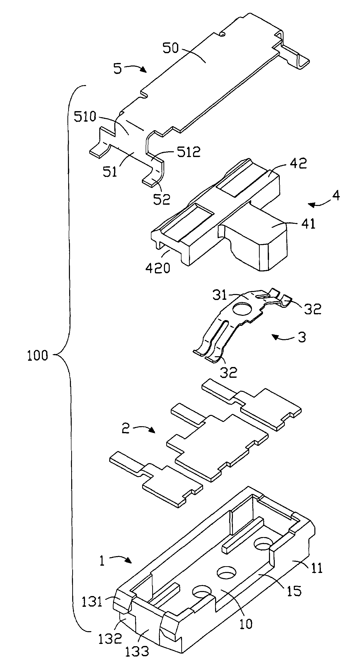
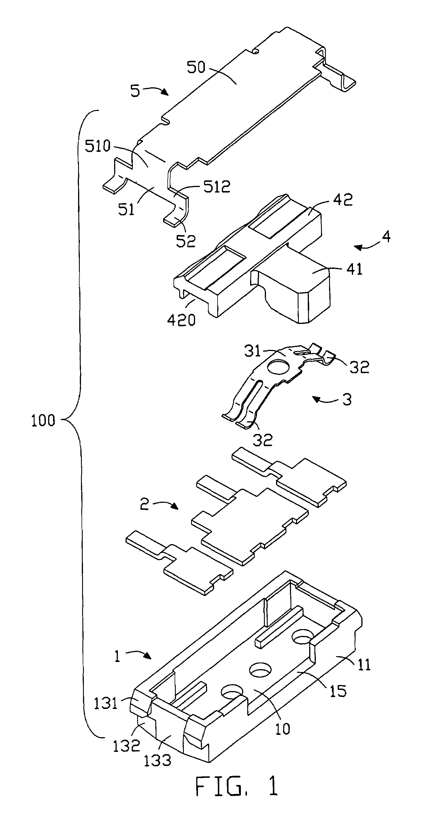
[0021]Referring to FIGS. 1-3, a slide switch 100 in accordance with the preferred embodiment of the present invention comprises a housing 1 with a bottom surface 10 and a plurality of side surfaces 11 around the bottom surface, a plurality of stationary contacts 2 embedded in the bottom surface of the housing 1, a slide member 4 moveably contained in the housing, a moveable contact fixed onto the slide member, and a cover 5 attached to the housing 1. The moveable contact 3 is fixed to said slide member 4 to be connected to and disconnected from said stationary contacts 2.

[0022]The housing 1 has a longitudinal configuration. The bottom surface 10 and the side surface 11 cooperatively define a cavity (not shown) with a top opening. One of the longitudinal side surfaces 11 defines a cut out 15 substantially at the middle thereof. The stationary contacts 2 are embedded in the bottom surface alon...


PUM


Abstract

A slide switch (100) comprises a housing (1), a plurality of stationary contacts (2) embedded in the housing, a slide member (4) moveably contained in the housing, a moveable contact (3) fixed to the slide member, and a cover (5) attached to the housing. The housing comprises a bottom surface (10) and a plurality of side surfaces (11) therearound, and said bottom surface and side surfaces cooperatively define a cavity. The moveable contact is fixed to said slide member to be connected to and disconnected from said stationary contacts. Each end of the housing defines a pair of protrusions (131) at upper portions of two lateral sides thereof, and therefore a channel is formed between said two protrusions. A pair of recesses (133) is defined below the protrusions respectively, and the recesses are recessed into the side surface of the end / channel.

Description

BACKGROUND OF THE INVENTION[0001]1. Field of the Invention[0002]The present invention relates to a slide switch for use in various electronic devices such as portable telephones and digital cameras.[0003]2. General Background[0004]Nowadays, slide switches are widely used in various electronic devices such as portable telephones and digital cameras.[0005]As shown in FIGS. 4-5, the conventional slide switch 100′ generally comprises an insulative housing 1′, a plurality of stationary contacts 2′ fixed in the housing, a slide member 4′ moveable mounted onto the housing, a moveable contact 3′ fixed onto the slide member, and a cover 5′ covering the housing and the slide member.[0006]The housing 1′ has a substantially longitudinal configuration with a top opening, and the housing comprises a bottom surface 10′ and a plurality of side surfaces 11′ around said bottom surfaces. Said bottom surface and side surfaces cooperatively define a cavity for accommodating the slide member. The station...

Claims


Application Information

Patent Timeline
IPC IPC(8): H01H15/06
CPCH01H9/04H01H15/06
InventorSUN, LIANG
OwnerHON HAI PRECISION IND CO LTD