Insert apparatus for a mold, method of manufacturing a structural unit, method of retrofitting an existing mold and a structural unit

a technology of inserting apparatus and mold, which is applied in the direction of foundation moulding apparatus, lighting and heating apparatus, application, etc., can solve the problems of deficient processes and molds, the limitation of how a concrete unit is manufactured by the mold, and the design placed on the vertical surface of the concrete unit would be removed or otherwise distorted, etc., to achieve the effect of being easily grasped, manipulated or otherwise transported on the site, and being convenient to us

Inactive Publication Date: 2009-08-18
R I LAMPUS
View PDF37 Cites 10 Cited by
  • Summary
  • Abstract
  • Description
  • Claims
  • Application Information

AI Technical Summary

Benefits of technology

[0011]It is, therefore, an object of the present invention to provide an insert apparatus, a method of manufacturing a structural unit, a method of retrofitting an existing mold and a structural unit that overcomes the deficiencies of the prior art. It is another object of the present invention to provide an insert apparatus, structural units and methods of manufacturing a structural unit that has an engagement portion on one or more of the vertical surfaces of the unit. It is yet another object of the present invention to provide an insert apparatus, structural units and methods of manufacturing these structural units that change the general dimensions of the unit. It is a still further object of the present invention to provide an insert apparatus for use in connection with a mold for manufacturing a structural unit that is simple in its use and does not remove or otherwise distort the engagement portion when the unit is removed from the mold. It is another object of the present invention to provide a method of manufacturing a structural unit that includes an engagement portion impressed or recessed upon a vertical side or sides of the unit that is more efficient and capable of mass manufacturing of such units. It is a still further object of the present invention to provide a method of retrofitting an existing mold, such that a structural unit can be produced having an engagement portion, in the form of a projection or a recess, thereon. It is another object of the present invention to provide a structural unit that is easily grasped, manipulated or otherwise transportable on a site.

Problems solved by technology

One drawback to applying a specific engagement portion or dimensioned projection or recess on a structural unit is the limitation of how a concrete unit is manufactured by the mold.
Therefore, any design that is placed upon a vertical surface of the concrete unit would be removed or otherwise distorted as the concrete unit drops down and slides through the mold via the pallet.
However, such processes and molds are deficient in that only a roughened or textured surface can be applied to the vertical face of the unit.
Therefore, such systems and processes are not capable of producing a specified engagement portion or design, which could not be removed or distorted as the concrete unit is discharged from the mold.
However, these molds and processes are quite complicated.
In addition, such intricate molds and machines are expensive and labor intensive, since multiple parts and walls and other mechanisms must be utilized to apply the indicia, remove the design portion and allow the block to be removed from the mold.
Further, such molds and processes may not be well suited for the mass production of structural units.
Therefore, while concrete or cinder blocks have a hollow core and may be grasped by these inner walls and moved about a construction site, the design of these prior art blocks makes them quite awkward to move and easily hold.

Method used


Image

  • Insert apparatus for a mold, method of manufacturing a structural unit, method of retrofitting an existing mold and a structural unit
  • Insert apparatus for a mold, method of manufacturing a structural unit, method of retrofitting an existing mold and a structural unit
  • Insert apparatus for a mold, method of manufacturing a structural unit, method of retrofitting an existing mold and a structural unit

Examples


Embodiment Construction

[0040]For purposes of the description hereinafter, the terms “upper”, “lower”, “right”, “left”, “vertical”, “horizontal”, “top”, “bottom”, “lateral” and derivatives thereof shall relate to the invention as it is oriented in the drawing figures. However, it is to be understood that the invention may assume various alternative variations and step sequences, except where expressly specified to the contrary. It is also to be understood that the specific devices and processes illustrated in the attached drawings, and described in the following specification, are simply exemplary embodiments of the invention. Hence, specific dimensions and other physical characteristics related to the embodiments disclosed herein are not to be considered as limiting.

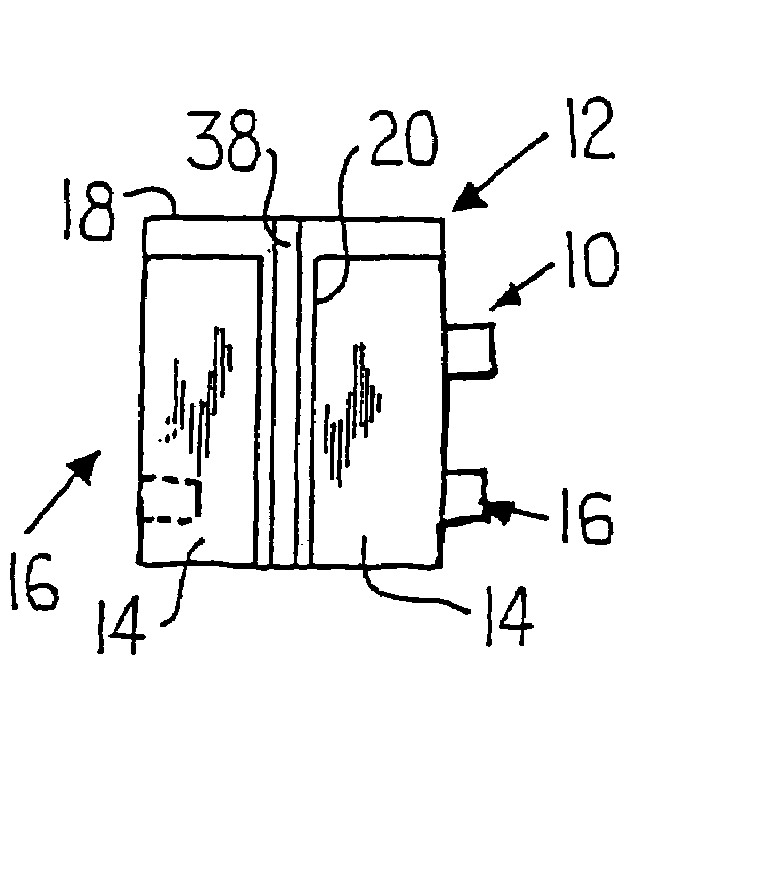
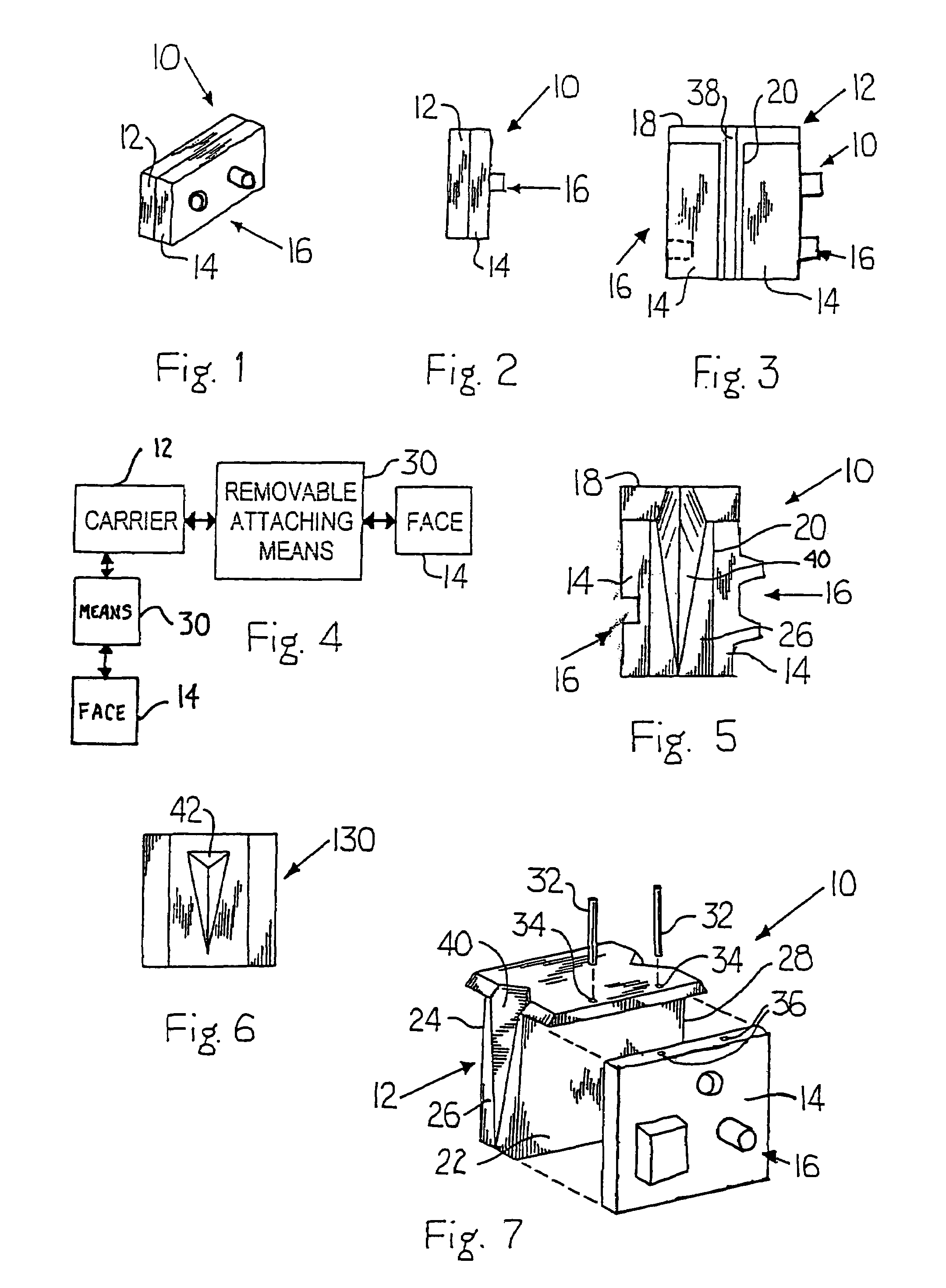
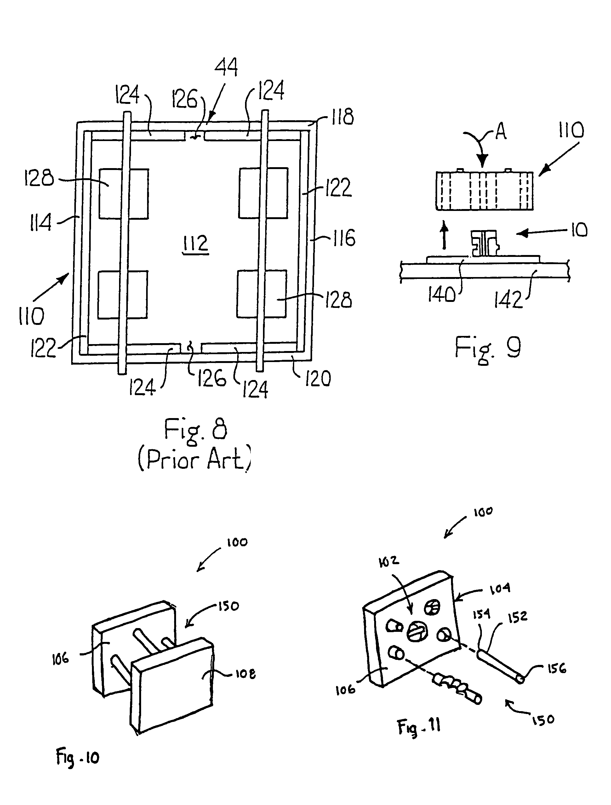
[0041]The present invention is directed to an insert apparatus 10, as shown in various embodiments in FIGS. 1-5 and 7, a method of manufacturing a structural unit 100, a method of retrofitting an existing mold 110 for manufacturing such a stru...


PUM

PropertyMeasurementUnit
physical propertiesaaaaaaaaaa
dimensionsaaaaaaaaaa
physical characteristicsaaaaaaaaaa

Abstract

Disclosed is an insert apparatus for a mold for manufacturing structural units. The insert apparatus includes a carrier for operatively engaging a portion of the mold, and is in communication with a face or an object having an engagement design portion thereon. The face is in operative communication with the carrier, and the engagement design portion extends into or out of the cavity of the mold. Methods of manufacturing such a structural unit, methods of retrofitting an existing mold for manufacturing such a unit and novel and improved structural units are also disclosed.

Description

CROSS REFERENCE TO RELATED APPLICATIONS[0001]This application is a continuation-in-part of U.S. patent application Ser. No. 10 / 897,823, filed Jul. 23, 2004, which claims the benefit of priority from U.S. Patent Application No. 60 / 489,987, filed Jul. 25, 2003, which is incorporated herein by reference in its entirety.BACKGROUND OF THE INVENTION[0002]1. Field of the Invention[0003]The present invention relates generally to apparatus and methods for manufacturing structural units, such as concrete blocks, brick, clay-based material, pavers, segmental retaining walls (SRWs), etc., from a mold and the structural units manufactured using these apparatus and methods and, in particular, to an insert apparatus for use in connection with a mold for manufacturing a structural unit, a method of manufacturing a structural unit having an engagement portion applied on a side or sides of the unit, a method of retrofitting an existing mold for manufacturing a structural unit having such engagement p...

Claims


Application Information

Patent Timeline
Patent Type & Authority Patents(United States)
IPC IPC(8): A23G9/00B28B7/06F25C1/24B28B7/00B28B7/34B28B7/36E04F21/04
CPCB28B7/0064E04F21/04B28B7/366B28B7/346
Inventor JUCHA, RICHARD R.LAMPUS, DONALD L.
Owner R I LAMPUS
Why Eureka
Try Eureka