

Power source apparatus
a power source and circuit technology, applied in the direction of electric variable regulation, process and machine control, instruments, etc., can solve the problem of increasing the cost of the power source apparatus
- Summary
- Abstract
- Description
- Claims
- Application Information
AI Technical Summary
Benefits of technology
Problems solved by technology
Method used
Image

Examples
Embodiment Construction
[0034]Exemplary embodiments of the present invention will be described in detail with reference to the drawings. It is noted that the embodiments do not limit this invention and all combinations of features described in the embodiments are not required for means for solving the problem of the invention. Components in the following embodiments include those that can be easily assumed by those skilled in the art and those having substantially the same structure. In the following embodiments, a case will be described where the 5-th harmonic component is reduced. However, the present invention is not limited to this and also can be applied to reduce a harmonic component having another order.
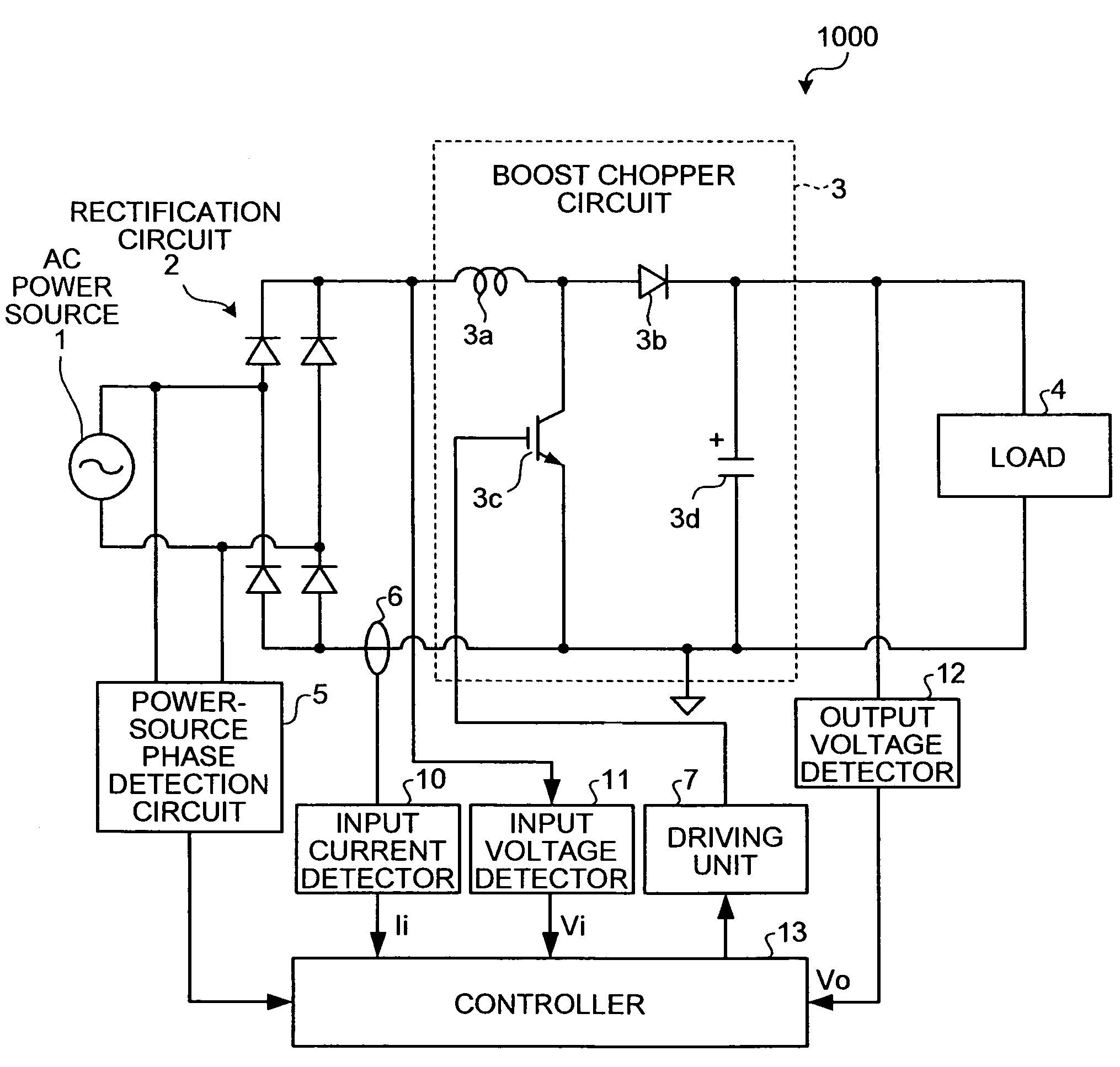
[0035]FIG. 1 is a schematic block diagram of a power source apparatus 1000 according to an embodiment of the present invention. According to the power source apparatus 1000, as in the conventional power source apparatus disclosed in Japanese Patent Application Laid-Open No. 2005-253284, an AC power s...
PUM
 Abstract
Description
Claims
Application Information