Actuating device

a technology of actuating device and actuator, which is applied in the direction of gearboxes, differential gearings, toothed gearings, etc., can solve the problems of increasing assembly and production costs, large number of components to be used and assembled, etc., and achieves the reliability of the actuating device, reduced production and assembly costs, and reduced assembly cost and the number of components.

Inactive Publication Date: 2009-09-01
PIERBURG GMBH & CO KG NEUSS
View PDF14 Cites 0 Cited by
  • Summary
  • Abstract
  • Description
  • Claims
  • Application Information

AI Technical Summary

Benefits of technology

[0005]It is therefore the object of the invention to realize an actuating device with a gear unit in which both the assembly cost and the number of components are to be distinctly reduced, and whereby reliable function of the actuating device is ensured, so that production and assembly costs are reduced.
[0006]This object is achieved in that a cover is fixed to the housing that tightly closes the drive unit and the gear unit on the outside and that is embodied in such a way that the bearing of the outwards-facing output shaft is embodied on one side and is arranged in the cover. Through such an embodiment according to the invention, the entire housing can be embodied in only two parts, since the necessity of a second bearing point of the output shaft and thus the necessity of the gear cage is eliminated. This results in easier access during assembly and a reduction in the number of components and the overall length of the gear unit. The bearing point of the output shaft in the cover is embodied sufficiently long to enable acceptance of any transverse forces that occur.
[0007]In a further form of embodiment, the gear unit features only one planetary gear that is arranged on an axle so that it can pivot, which axle is fixed to and supported by a motor end shield, in which shield the gear-side bearing of the motor shaft serving as drive shaft is also arranged. The motor end shield can be connected firmly to the housing of the electric motor. In addition to the consequent reduction in the number of components needed, the fixing of the motor end shield to the housing causes an improvement in the dynamic strength of the actuating device. Moreover, assembly is distinctly facilitated, since the components can simply be placed on top of one another. Through the single double toothed gear, the demands on the manufacturing tolerances in particular of the parallelism of the axles are reduced, so that production costs can be saved.
[0008]In a preferred form of embodiment, the axle of the double toothed gear is supported in the cover on the side opposite the motor end shield and the internal gear or internal gear segment features a corresponding recess, by means of which occurring transverse forces in the gear and in particular at the double toothed gear can be counteracted by the two-sided bearing of the axle, without having to use additional components.

Problems solved by technology

The disadvantage of such a form of embodiment is the large number of components to be used and assembled, whose sizes must be matched to one another very precisely.
This results in increased assembly and production costs, since the respective axles of the double toothed gears, the drive shaft, and the output shaft must be matched to one another very precisely, that is to say a smaller tolerance must be maintained with respect to their parallel position to one another.

Method used


Image

  • Actuating device
  • Actuating device

Examples


Embodiment Construction

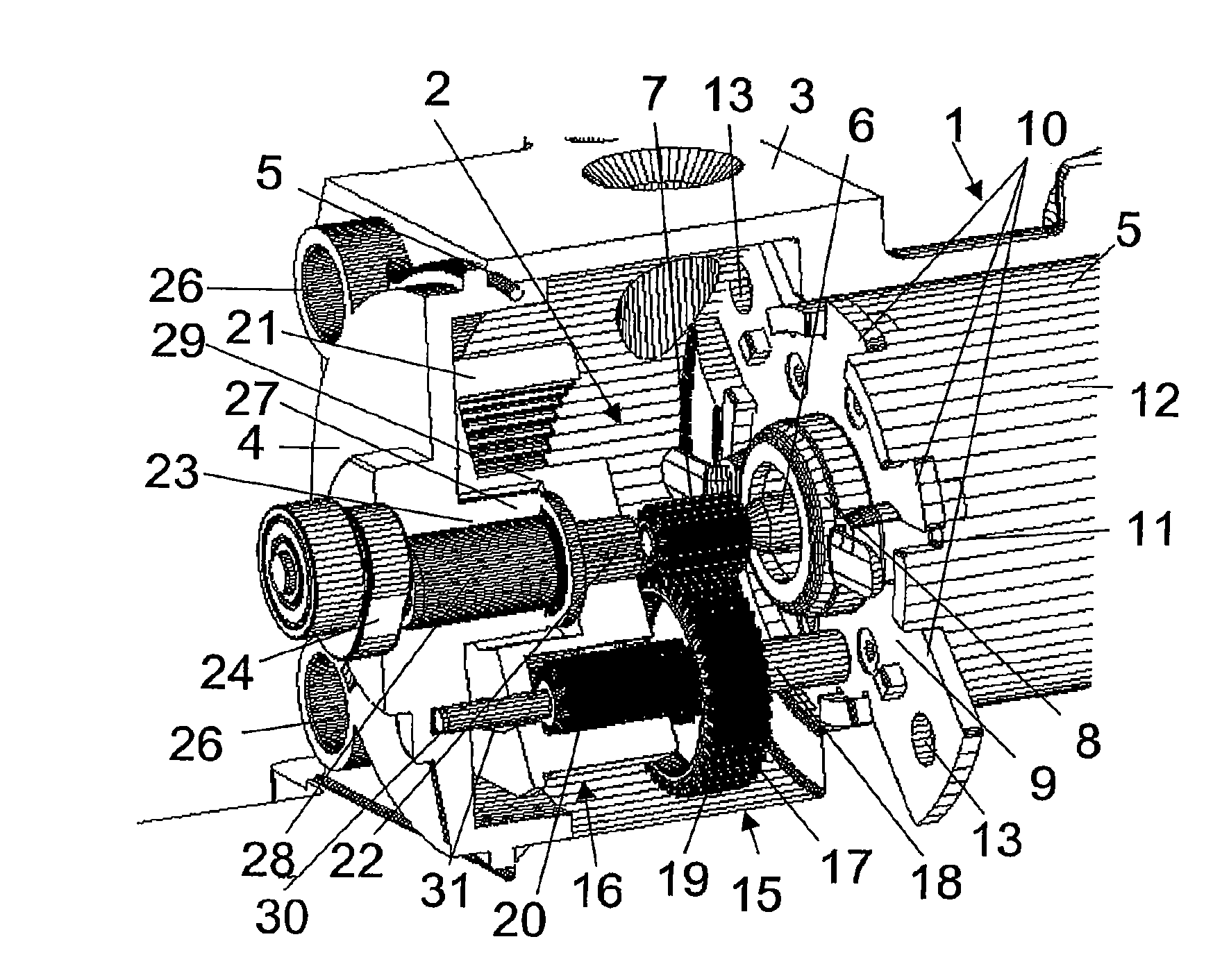
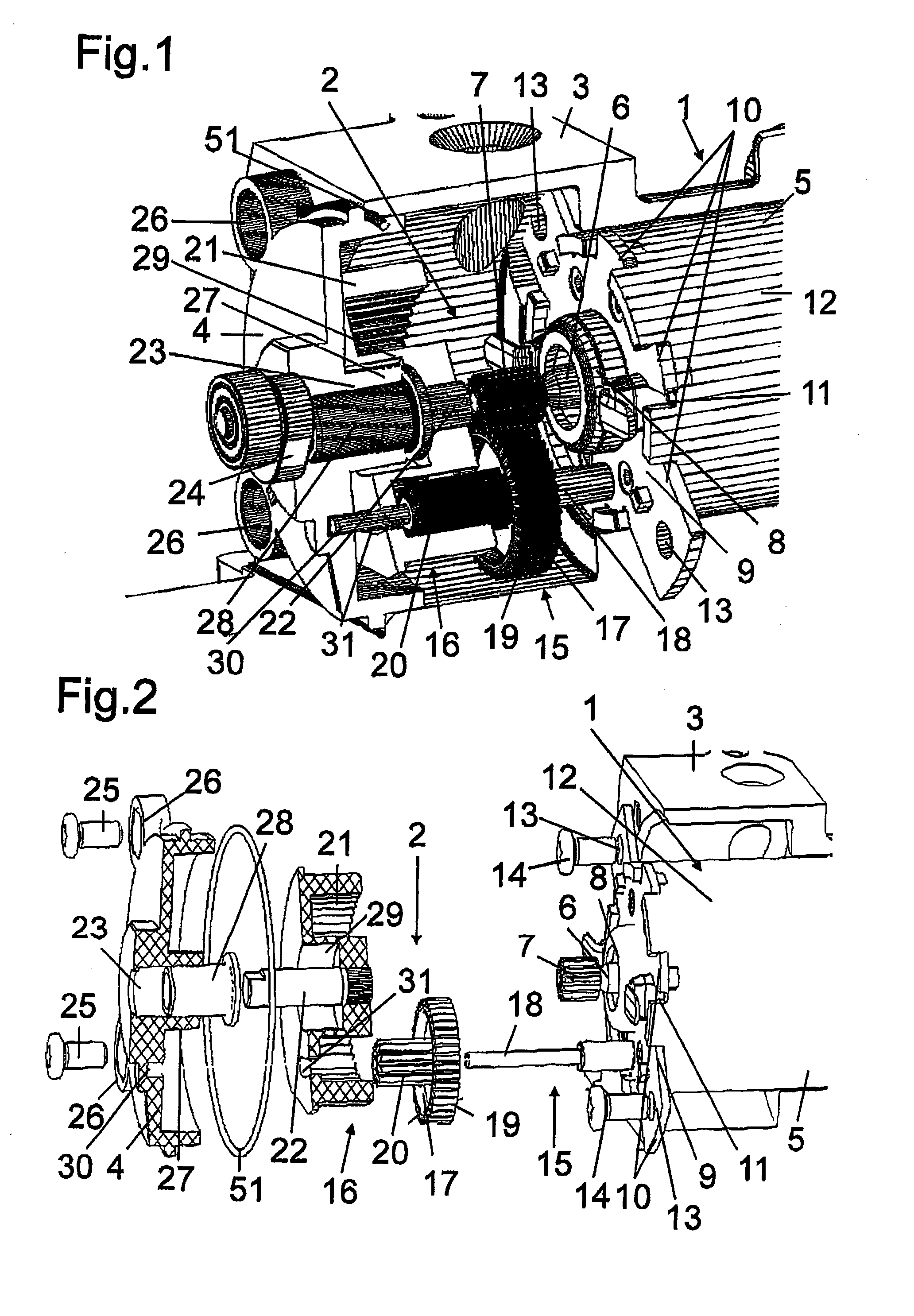
[0013]The actuating device according to the invention shown in FIG. 1 comprises a drive unit 1 and a gear unit 2, which are arranged in a housing 3. The housing 3 is essentially embodied in the shape of a pot and is tightly closed on the output side by a cover 4 with the interposition of a seal 51.

[0014]The drive unit 1 comprises an electric motor 5, on whose drive shaft 6 a drive gear 7 is arranged at least in a rotationally fixed manner. The drive shaft 6 is supported via a bearing point 8 arranged in a motor end shield 9. This motor end shield 9 features protuberances 10 that engage in corresponding recesses 11 of a pole tube 12 of the motor 5, so that the pole tube 12 is arranged in a rotationally fixed manner to the gear unit 2. Some of these protuberances 10 also feature boreholes 13, via which the motor end shield 9 and thus the electric motor 5 can be fixed to the housing 3 by means of screws 14. When a brushed motor is used, it is moreover possible to attach holders for com...


PUM


Abstract

An actuating device including a housing that is closed by a cover in such a way that both an electric motor and a gearbox unit are completely enclosed. An internal gear segment, arranged on an output shaft in a rotationally fixed manner, is positioned on a borehole of the cover. An axle on which a double toothed gear is arranged is then mounted on the output side, an a pocket hole in the cover. This reduces the overall length, as well as the number of components and the cost.

Description

[0001]This is a National Phase Application in the United States of International Patent Application No. PCT / EP2004 / 011047 filed Oct. 4, 2004, which claims priority on German Patent Application No. 103 46 403.4, filed Oct. 7, 2003. The entire disclosures of the above patent applications are hereby incorporated by reference.BACKGROUND OF THE INVENTION[0002]The invention relates to an actuating device with a drive unit that features an electric motor, which motor is arranged in a housing and drives a drive shaft, and with a gear unit that features a drive gear arranged on the drive shaft at least in a rotationally fixed manner, which drive gear in a first gear stage meshes with at least one planetary gear that is embodied as a double toothed gear and is supported on an axle in a fixed position and so that it can pivot, whereby the drive gear drives the larger gear wheel of the double toothed gear, and the smaller gear wheel, which faces the direction of the output side, in a second gea...

Claims


Application Information

Patent Timeline
Patent Type & Authority Patents(United States)
IPC IPC(8): F16H48/06F16H57/02F16H57/023F16H57/025F16H57/031
CPCF16H57/023F16H57/025F16H57/031Y10T74/19651F16H2057/02034F16H2057/02095
Inventor KOSTER, ANDREASDISMON, HEINRICHVITT, STEFAN
Owner PIERBURG GMBH & CO KG NEUSS
Why Eureka
Try Eureka