Universal clamp

a universal clamp and assembly technology, applied in the field of universal clamps, can solve the problems of wasting time and material, inability to perform line maintenance with separate insulators and clamps, and inability to accommodate a variety of sizes without interchanging parts, so as to prevent abrasion of conductors and minimize corrosion.

Inactive Publication Date: 2009-09-15
HUBBELL INC
View PDF30 Cites 14 Cited by
  • Summary
  • Abstract
  • Description
  • Claims
  • Application Information

AI Technical Summary

Benefits of technology

[0008]Still another object is to provide a universal clamp with a bolt allowing the clamp to swivel about the axis of the bolt without passing completely through the support fitting.
[0010]Yet another object is to provide a universal clamp having a clamp member with the two outwardly flaring and curved ends that face away from the conductor to minimize corrosion and prevent abrasion of the conductor.

Problems solved by technology

Conventional clamp and insulator assemblies are unable to accommodate a variety of sizes without interchanging parts.
Common mechanical clamps used in conjunction with insulators as a multi-piece system present a number of problems, including wasting time and material.
Another issue is the difficulty of performing line maintenance with separate insulators and clamps because the use of removable bolts and washers increases the chances of a lineman dropping parts during installation or losing parts during storage and handling operations.

Method used


Image

  • Universal clamp
  • Universal clamp
  • Universal clamp

Examples


Embodiment Construction

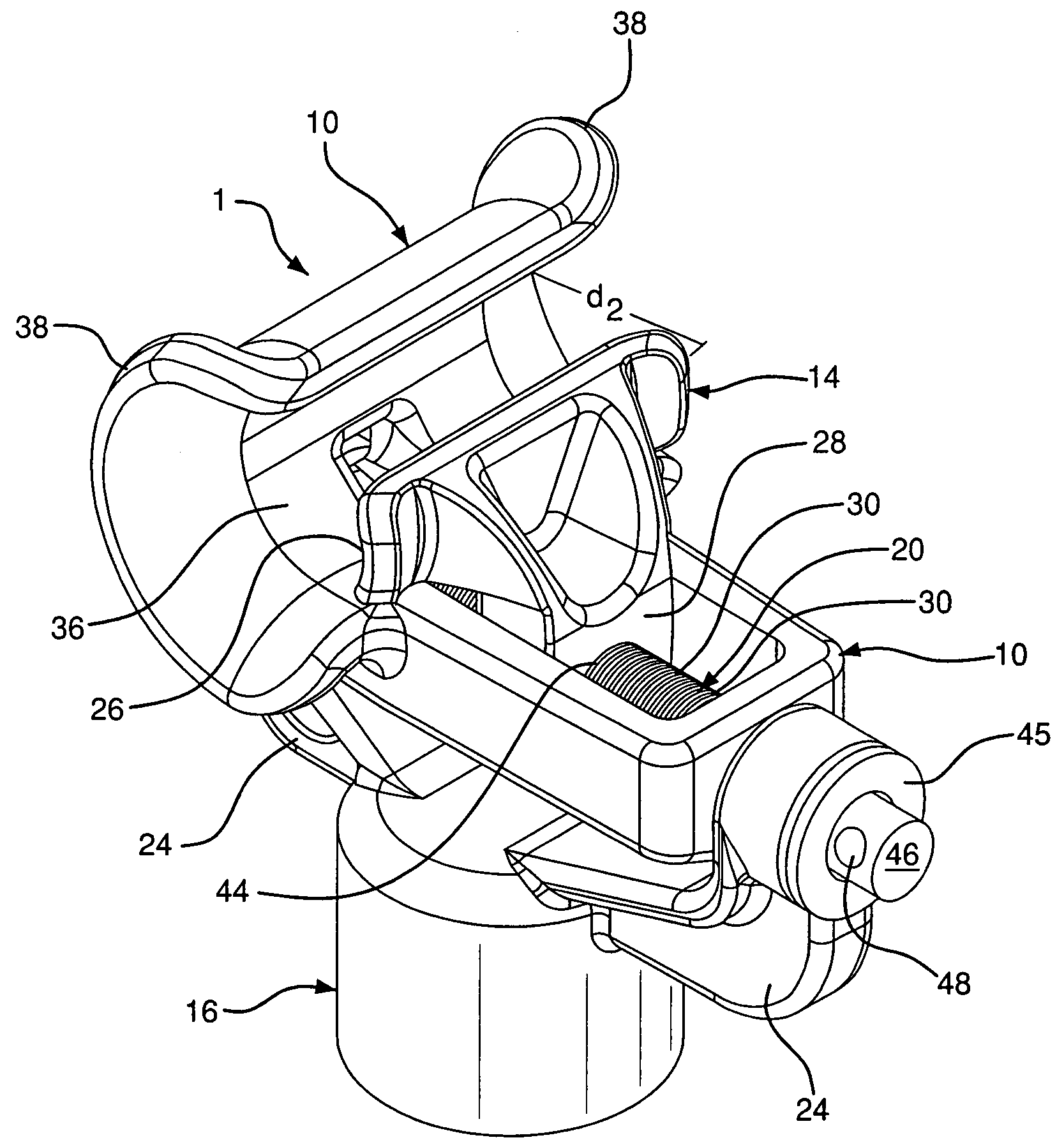
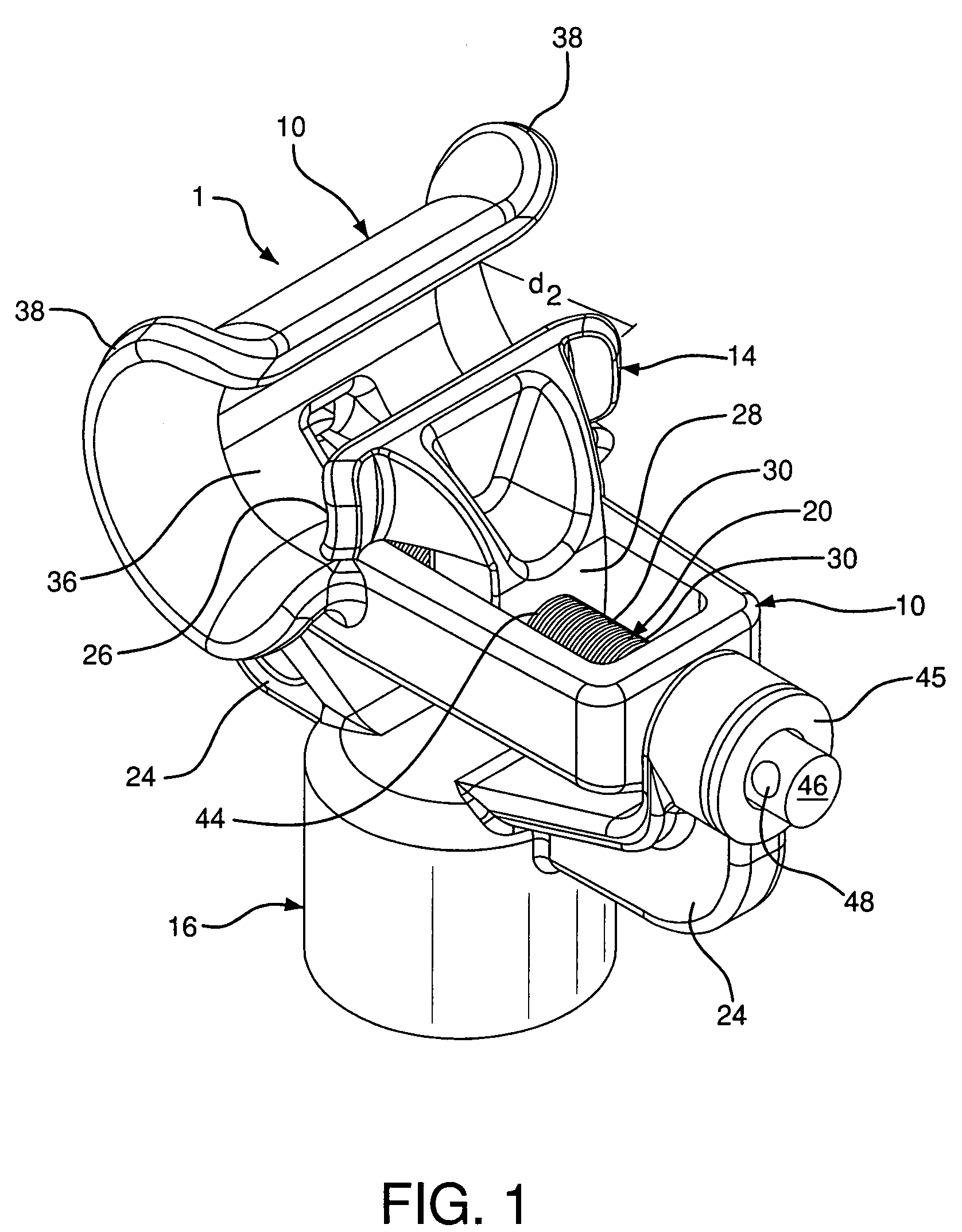
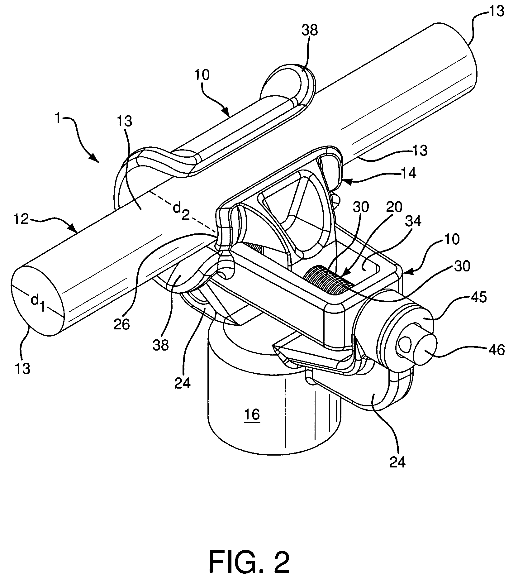
[0022]As seen in FIGS. 1-3, a universal clamp assembly 1 includes a support fitting 16 with first and second arms 24 and a threaded bolt 20 mounted to the arms 24 for rotation about a longitudinal axis of the bolt 20. The bolt 20 is retained against axial movement along the longitudinal axis. The clamp assembly 1 further includes a clamp member 10 rotatably mounted on the bolt 20 between the arms 24 for allowing rotation of the clamp member 10 relative to the support fitting 16 about the longitudinal axis. The clamp member 10 is restrained against axial movement relative to the support fitting 16 and the bolt 20 along the longitudinal axis. The clamp member 10 includes a guide opening 34 through which the bolt 20 extends. A keeper 14 is threadedly mounted on the bolt 20 and partially received in the guide opening 34. The keeper 14 slides in the guide opening 34 along the longitudinal axis and is restrained against rotation about the longitudinal axis relative to the clamp member 10....


PUM


Abstract

A universal clamp assembly having a support fitting with arms and a threaded bolt mounted to the arms allowing rotation about a longitudinal axis of the bolt. The bolt is retained against axial movement along the longitudinal axis. A clamp member is rotatably mounted on the bolt between the arms for rotation of the clamp member relative to the support fitting about the longitudinal axis. The clamp member is restrained against axial movement relative to the support fitting and the bolt along the longitudinal axis. The clamp includes a guide opening through which the bolt extends. A keeper is threadedly mounted on the bolt and partially received in the guide opening. The keeper slides in the guide opening along the longitudinal axis and is restrained against rotation about the longitudinal axis of the bolt relative to the clamp member. The keeper is rotatable about the longitudinal axis concurrently with the clamp member.

Description

FIELD OF THE INVENTION[0001]The present invention relates to a universal clamp assembly for receiving electrical conductors of various diameters without interchanging parts. More particularly, the invention relates to a clamp assembly having a support fitting with two arms, a threaded bolt mounted to the arms and a clamp member rotatably mounted on the bolt allowing rotation of the clamp member. A keeper is threadedly mounted on the bolt and partially received in a guide opening of the clamp. The keeper moves back and forth along the track of the bolt towards and away from a saddle portion of the clamp member. The bolt allows the saddle and keeper to swivel about the axis of the bolt for horizontal and vertical mounting of the clamp assembly.BACKGROUND OF THE INVENTION[0002]Conventional clamp and insulator assemblies are unable to accommodate a variety of sizes without interchanging parts. Common mechanical clamps used in conjunction with insulators as a multi-piece system present a...

Claims


Application Information

Patent Timeline
Patent Type & Authority Patents(United States)
IPC IPC(8): A47B96/06
CPCH01B17/06
Inventor BERNSTORF, ROBERT A.VAN BESOUW, BASTIAAN H.THOMAS, JEFFERY L.LEE, MICHAEL J.BATES, MATTHEW M.SANCHEZ, GUALBERTO J.TAMM, CARL R.HESSON, RICHARD J.
Owner HUBBELL INC
Why Eureka
Try Eureka