Portable power working machine

a working machine and portable technology, applied in the direction of portable power-driven tools, magnetic circuit rotating parts, shape/form/construction, etc., can solve the problems of reducing the endurance of the electric motor, and affecting the operation of the operating arm in the front-rear and left-right directions. the effect of reducing the burden on the operator

Inactive Publication Date: 2010-01-12
SUBARU CORP
View PDF9 Cites 24 Cited by
  • Summary
  • Abstract
  • Description
  • Claims
  • Application Information

AI Technical Summary

Benefits of technology

[0013]In light of the above-described situation, an object of the present invention is to provide a portable power working machine with high operability, endurance, and cooling performance for a drive source, such as an electric motor.

Problems solved by technology

Therefore, it is difficult to move the distal end of the operating arm in the front-rear and left-right directions.
Therefore, foreign matters such as dust generated when weeds and the like are cut by the rotating cutting blade tend to enter the motor housing through the outlet.
These foreign matters cause abrasion of rotating components, such as bearings, and reduce endurance of the electric motor.
In addition, the outlet is easily clogged with weeds and the like that are cut by the cutting blade.
If this happens, the flow of the cooling air is degraded and performance in cooling the electric motor and the like is reduced.
Furthermore, the battery and the electric motor must be connected to each other with long wires, which requires cumbersome tasks of wiring and maintenance.
In addition, a battery with a large capacity is required, and use of such a battery leads to an increase in the weight of the bush cutter.
These problems occur not only in bush cutters, but also in other kinds of portable power working machines having an electric motor and an actuating part at a distal end of an operating arm.

Method used


Image

  • Portable power working machine
  • Portable power working machine
  • Portable power working machine

Examples


Embodiment Construction

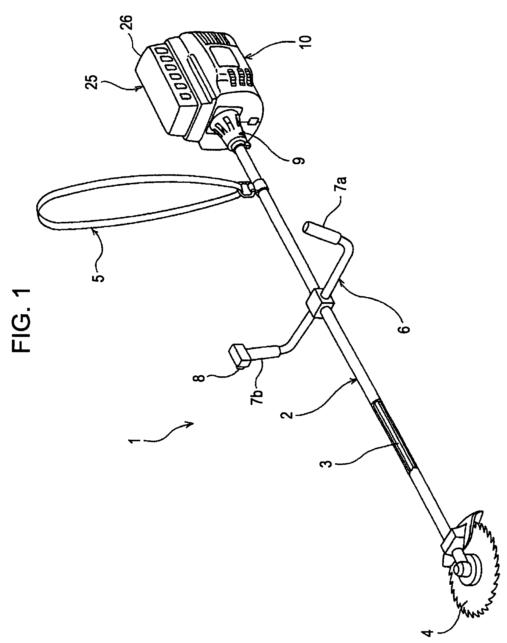
[0035]A bush cutter will be explained below with reference to FIGS. 1 to 5 as a portable power working machine according to an embodiment of the present invention.

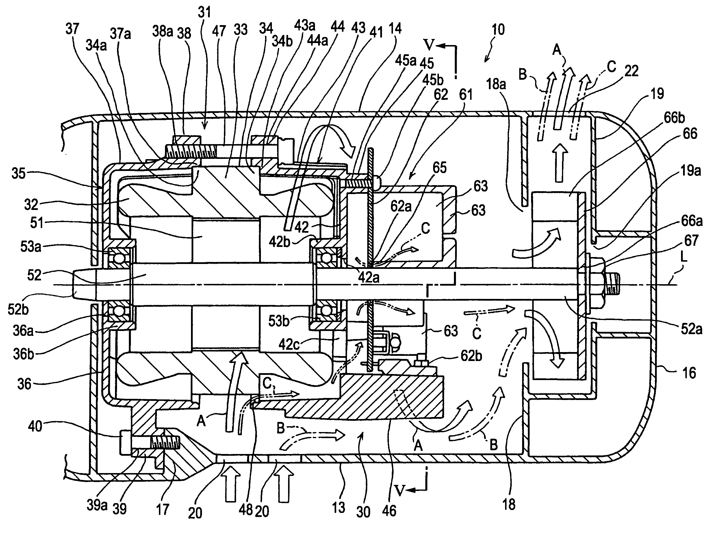
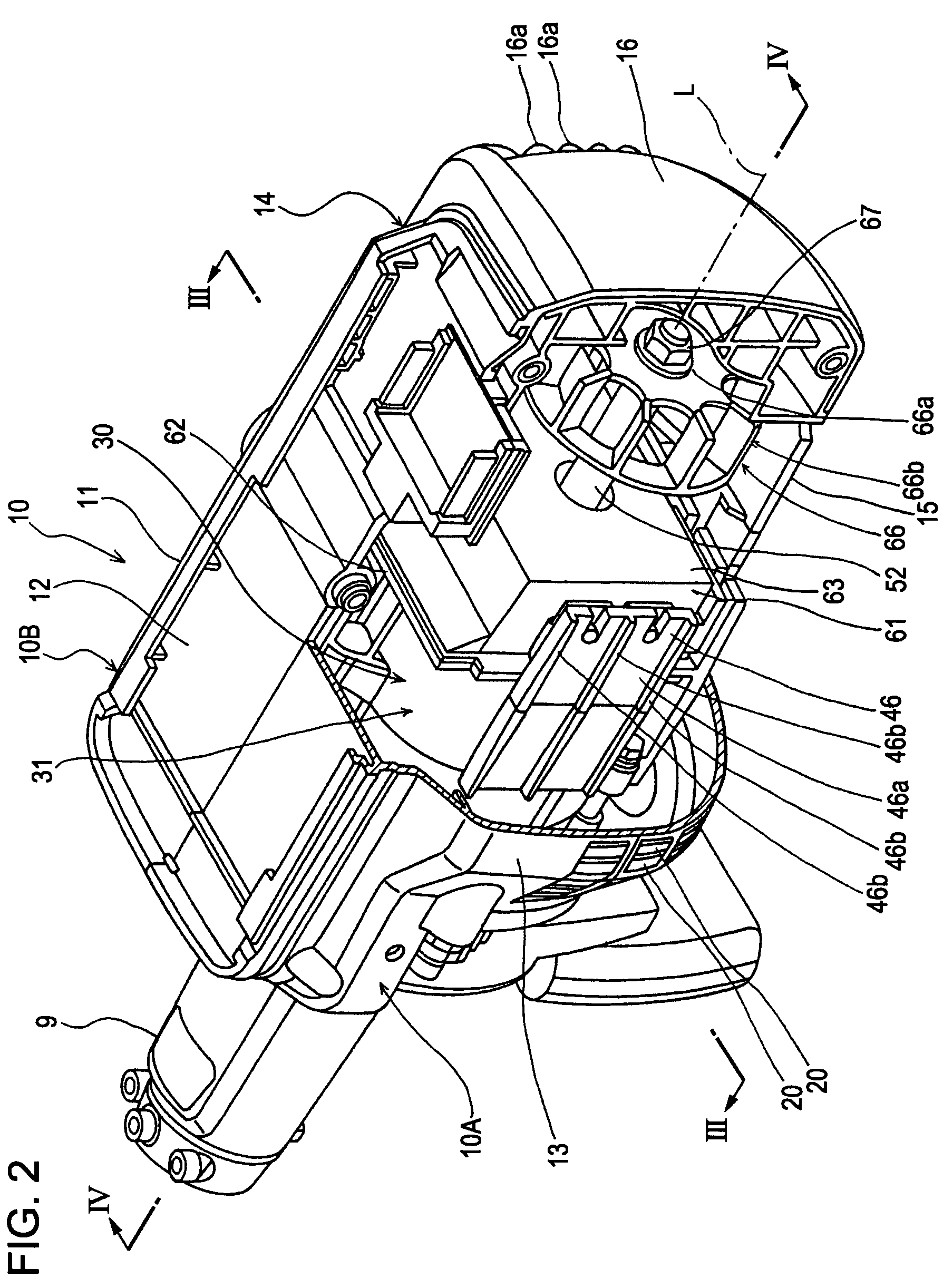
[0036]First, the external appearance of a bush cutter 1 according to the present embodiment will be described. FIG. 1 is a perspective view of the bush cutter 1 according to the present embodiment. The bush cutter 1 includes a pipe-shaped elongated operating arm 2, a drive shaft 3 extending through the operating arm 2, and a motor housing 10. A front end of the motor housing 10 is attached to a proximal end of the operating arm 2 with a joint 9. The motor housing 10 contains a drive unit 30, which will be described below, and the drive unit 30 includes an electric motor 31 that rotates the drive shaft 3. A cutting blade 4, which corresponds to an actuating part, provided at a distal end of the operating arm 2 is rotated by the rotation of the drive shaft 3.

[0037]The operating arm 2 has a loop-shaped shoulder strap 5, which...


PUM


Abstract

A portable power working machine includes a drive unit disposed in a motor housing connected to a proximal end of an operating arm. The drive unit rotates a cutting blade at a distal end of the operating arm. The motor housing has an inlet and an outlet for cooling air in front and rear sections, respectively. The drive unit includes an electric motor disposed near the front end of the motor housing, a cooling fan disposed near the rear end of the motor housing and connected to an output shaft of the electric motor, and a heat sink disposed between the cooling fan and the electric motor so as to extend from the electric motor. The cooling air drawn in through the inlet by the cooling fan is guided through a gap between the drive unit and an inner surface of the motor housing and is discharged through the outlet.

Description

CROSS REFERENCE TO RELATED APPLICATIONS[0001]The disclosure of Japanese Application No. 2006-270425 filed on Oct. 2, 2006 including the specification, drawings, and abstract is incorporated herein by reference in its entirety.BACKGROUND OF THE INVENTION[0002]1. Field of the Invention[0003]The present invention relates to a portable power working machine, such as a bush cutter, that drives an actuating part, such as a cutting blade, provided at a distal end of an operating arm with an electric motor.[0004]2. Description of the Related Art[0005]Portable power working machines, such as portable bush cutters, are generally used for cutting weeds on footpaths between fields, undergrowth and grass in forests, etc.[0006]As an example of this type of bush cutter, Japanese Unexamined Patent Application Publication No. 2004-8054 discloses a bush cutter including a pipe-shaped operating arm, a drive shaft extending through the operating arm, an engine provided at a proximal end of the operatin...

Claims


Application Information

Patent Timeline
Patent Type & Authority Patents(United States)
IPC IPC(8): H02K9/06H02K9/26
CPCH02K9/22H02K11/0073H02K5/20H02K7/145H02K9/06B25F5/008H02K11/33A01G3/088H02K5/207H02K9/227
Inventor YOSHIDA, KENICHITOMIYAMA, HIDEKIYOSHIMURA, MASANOBUSUZUKI, TOSHIYUKI
Owner SUBARU CORP
Why Eureka
Try Eureka