Submersible hollow shaft motor and submersible floating aerator comprising the same

a technology of submersible hollow shaft and floating aerator, which is applied in the direction of wind motor components, non-positive displacement fluid engines, liquid fuel engine components, etc., can solve the problems of high horsepower, high maintenance cost of rotor systems, and high utilization of oxygen, so as to achieve high utilization of oxygen and improve maintenance cost , the effect of large aeration depth

Active Publication Date: 2010-02-16
SUN SHULIN +1
View PDF23 Cites 8 Cited by
  • Summary
  • Abstract
  • Description
  • Claims
  • Application Information

AI Technical Summary

Benefits of technology

[0008]In view of the above-described problems, it is one objective of the invention to provide a submersible hollow shaft motor that overcomes the failure problem caused by high operating temperature. Another objective of the invention is to provide a submersible floating aerator that features large aeration depth, high utilization of oxygen, and uniform gas distribution.

Problems solved by technology

They require high horsepower and consume high amounts of energy to pump liquids against the force of gravity.
Rotor systems have been known to be expensive to maintain and are high in energy consumption.
The problems with conventional aerators include limited depth of aeration, low utilization of oxygen, and non-uniform gas distribution.
Moreover, the motors of conventional aerators are located above the liquid level, and are prone to failure due to high operating temperatures.

Method used


Image

  • Submersible hollow shaft motor and submersible floating aerator comprising the same
  • Submersible hollow shaft motor and submersible floating aerator comprising the same
  • Submersible hollow shaft motor and submersible floating aerator comprising the same

Examples


Embodiment Construction

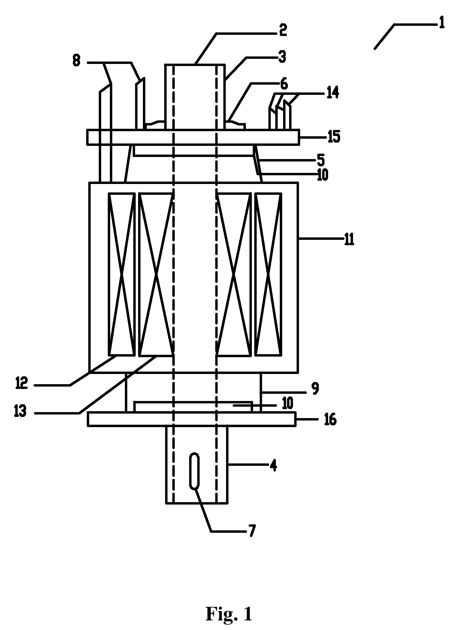
[0049]As shown in FIG. 1, a submersible hollow shaft motor comprises a hollow shaft 2, a top oil chamber 5, a middle oil chamber 11, a bottom oil chamber 9, a top shaft extension 3, and a bottom shaft extension 4. A sand-throwing ring 6 is disposed between the top shaft extension 3 and the top oil chamber 5. A keyway 7 is disposed at one end of the bottom shaft extension 4. A pair of mechanical seals 10 is disposed, one in the top oil chamber 5 and one in the bottom oil chamber 9. A stator 12 and a rotor 13 are disposed in the middle oil chamber 11. A cable 14 is connected to the middle oil chamber 11, and passes through the top oil chamber 5 and the mechanical seal 10. The top oil chamber 5, the middle oil chamber 11 and the bottom oil chamber 9 are connected to the air above water via a pipe 8.

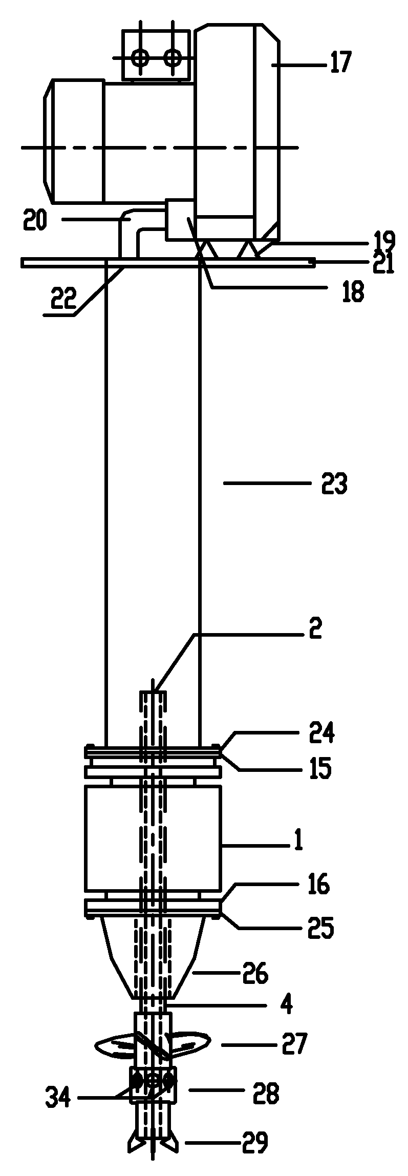
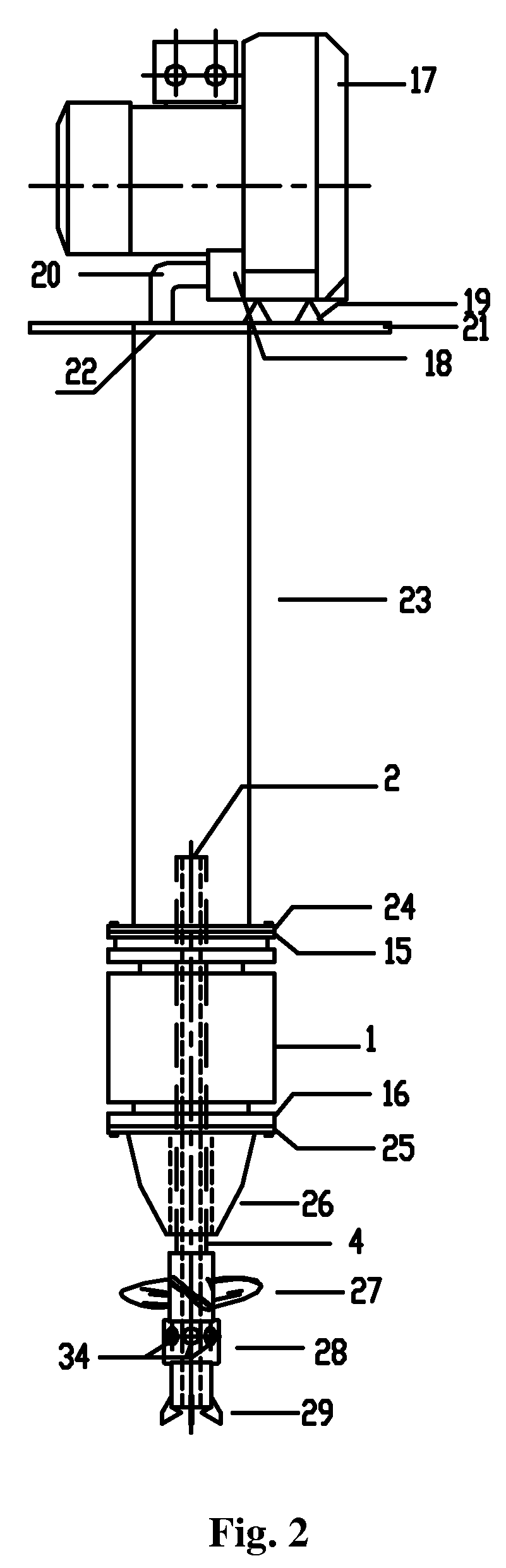
[0050]As shown in FIGS. 2 and 4, a submersible floating aerator comprises a submersible hollow shaft motor 1, a second flange 25, a gas-ring compressor 17, a base 21, a gas inlet tube 23, a ...


PUM

PropertyMeasurementUnit
angleaaaaaaaaaa
angleaaaaaaaaaa
force of gravityaaaaaaaaaa

Abstract

Provided is a submersible floating aerator, including a submersible hollow shaft motor (1) including a hollow shaft (2), a bottom shaft extension (4), a first motor flange (15), a second motor flange (16), a first flange (24) and a second flange (25), a gas-ring compressor (17), a base (21) having a gas inlet hole (22), a gas inlet tube (23), a dome (26), a propeller assembly (60) and an air outlet opening (18); wherein the base (21) is fixed on the top of the gas inlet tube (23), the gas-ring compressor (17) is fixed on the base (21) via a bracket (19); the air outlet opening (18) is connected to the gas-inlet hole (22) via a pipe (20); the gas inlet tube (23) is fixed to the first motor flange (15) via a first flange (24); the second motor flange (16) is fixed to the dome (26) via the second flange (25); the bottom shaft extension (4) is coaxially connected to the propeller assembly (60); and the hollow shaft (2) rotates along with the propeller assembly (60). The submersible floating aerator features large aeration depth, high utilization of oxygen, and uniform gas distribution.

Description

CROSS-REFERENCE TO RELATED APPLICATIONS[0001]This application claims priority to Chinese Patent Application No. 200610168196.0 filed on Dec. 15, 2006, the contents of which are incorporated herein by reference.BACKGROUND OF THE INVENTION[0002]1. Field of the Invention[0003]The invention relates to a submersible hollow shaft motor and to a submersible floating aerator comprising a submersible hollow shaft motor.[0004]2. Description of the Related Art[0005]Liquid aeration is used in the treatment of liquids for the purpose of mixing in air and increasing the dissolved oxygen (DO) content of the liquids. When liquid aeration is used as part of a wastewater treatment, bacteria and other microorganisms are usually added to the liquid as well to breakdown organic matter within the wastewater. In other applications, aeration processes are used in the treatment of water to meet the dissolved oxygen requirements for supporting fish and other aquatic organisms, for example, in aquaculture.[00...

Claims


Application Information

Patent Timeline
Patent Type & Authority Patents(United States)
IPC IPC(8): B01F3/04
CPCB01F3/04539B01F3/04588B01F7/00341B01F7/00733C02F3/205B01F13/0049Y02W10/15B01F2003/04546B01F2003/04723Y10S261/47Y02W10/10B01F23/2331B01F23/23311B01F23/2332B01F23/23367B01F27/113B01F27/25B01F33/503
Inventor SUN, SHULINSUN, JIAN
Owner SUN SHULIN
Why Eureka
Try Eureka