Pneumatic radial tire with specified belt layer

a technology of pneumatic radial tire and belt layer, which is applied in the direction of yarn, transportation and packaging, and other domestic articles, can solve the problems of poor properties of aircraft radial tire, excessive thickness of tread side region, and easy damage of tire, so as to ease tension and avoid separation

Active Publication Date: 2010-05-11
BRIDGESTONE CORP
View PDF14 Cites 10 Cited by
  • Summary
  • Abstract
  • Description
  • Claims
  • Application Information

AI Technical Summary

Benefits of technology

[0351]Next, in order to make sure the effect of the invention, one type of a conventional pneumatic radial tire, four types of comparative example pneumatic radial tires, and 13 types of pneumatic radial tires to which the embodiments of the present invention was applied were prepared, and the weight, the diameter growth rate, cut resistance and pressure tightness of each tire were checked. The size of each tire is 1270×455R22 32PR.
[0353]Tire weight: the tire weight is expressed using indices in which the conventional tire is set to 100. As the numerical value is smaller, the weight is lighter.
[0354]Tire diameter growth rate: an outer diameter increasing rate of a tire center portion was checked before and after the air pressure was charged. As the increasing rate is smaller, the tension of the tread rubber layer is smaller.
[0355]The air pressure of MEASURING RIM and INFRATION PRESSURE defined in a YEARBOOX of 2002 of “TIRE and RIM ASSOCIATION (TRA)” were used. Here, the air pressure is 1620 kPa.
[0356]Cut resistance: a cutter having a width of 40 mm and a blade tip angle of 30° was pushed against a tire center portion of a tread vertically in the widthwise direction, and a cut depth was checked.(Definition of Specified Load)

Problems solved by technology

Therefore, when the tire rides over foreign matter, the aircraft radial tire is poor in properties by which a tread thereof is not damaged when the entire tire rides over the foreign matter, i.e., so-called “enveloping properties”.
In a state in which the tread rubber of the tire is expanded in the circumferential direction of the tire, a resistance force against the foreign matter becomes weak, and there is a problem that the trampled foreign matter easily enters the tread, and the tire is prone to be damaged.
According to the conventional technique as shown in FIG. 22, however, by securing a necessary rubber thickness H (thickness of rubber only and thickness of cord is not included) in the tread central region where the total thickness of the belt layer becomes most thick, there are problems that a rubber thickness H0 of the tread side region becomes excessively thick and thus, the tire weight is increased forcibly, a heating value of the tread side region is increased and thus, the high speed endurance is lowered.
In the conventional belt structure, only by using a relatively high elastic cord in the belt ply, performance in which the cord characteristics are sufficiently exhibited can not be obtained, and it is difficult to reduce the weight of members to be used as light as possible.

Method used


Image

  • Pneumatic radial tire with specified belt layer
  • Pneumatic radial tire with specified belt layer
  • Pneumatic radial tire with specified belt layer

Examples


first embodiment

[0220]One example of a mode for carrying out the present invention will be described with reference to the drawings below.

[0221]A pneumatic radial tire of a first embodiment of the present invention will be described with reference to FIGS. 1 to 5.

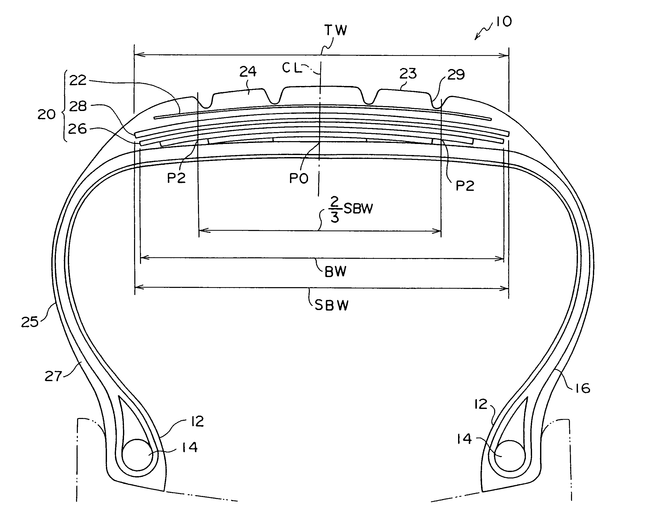
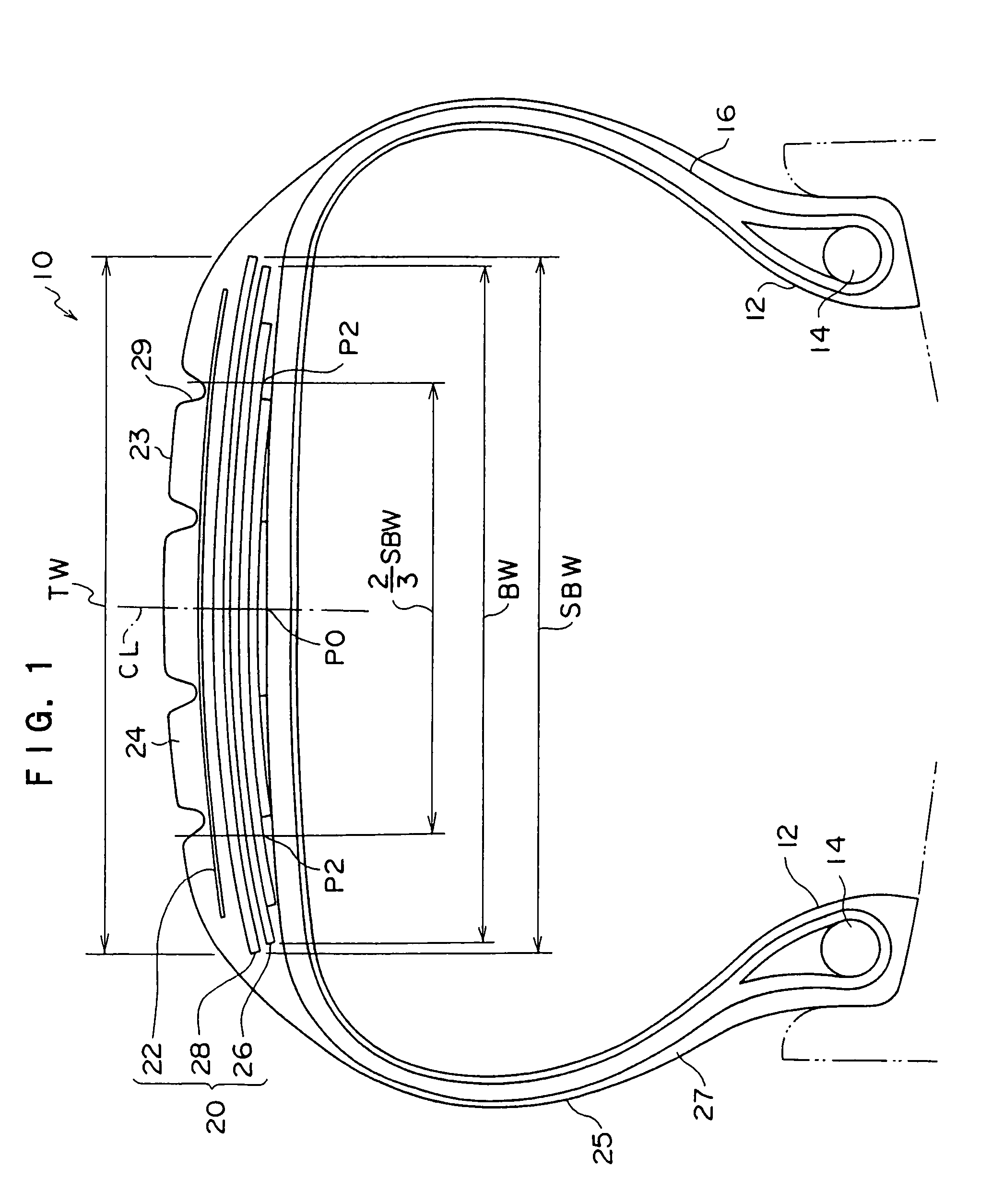
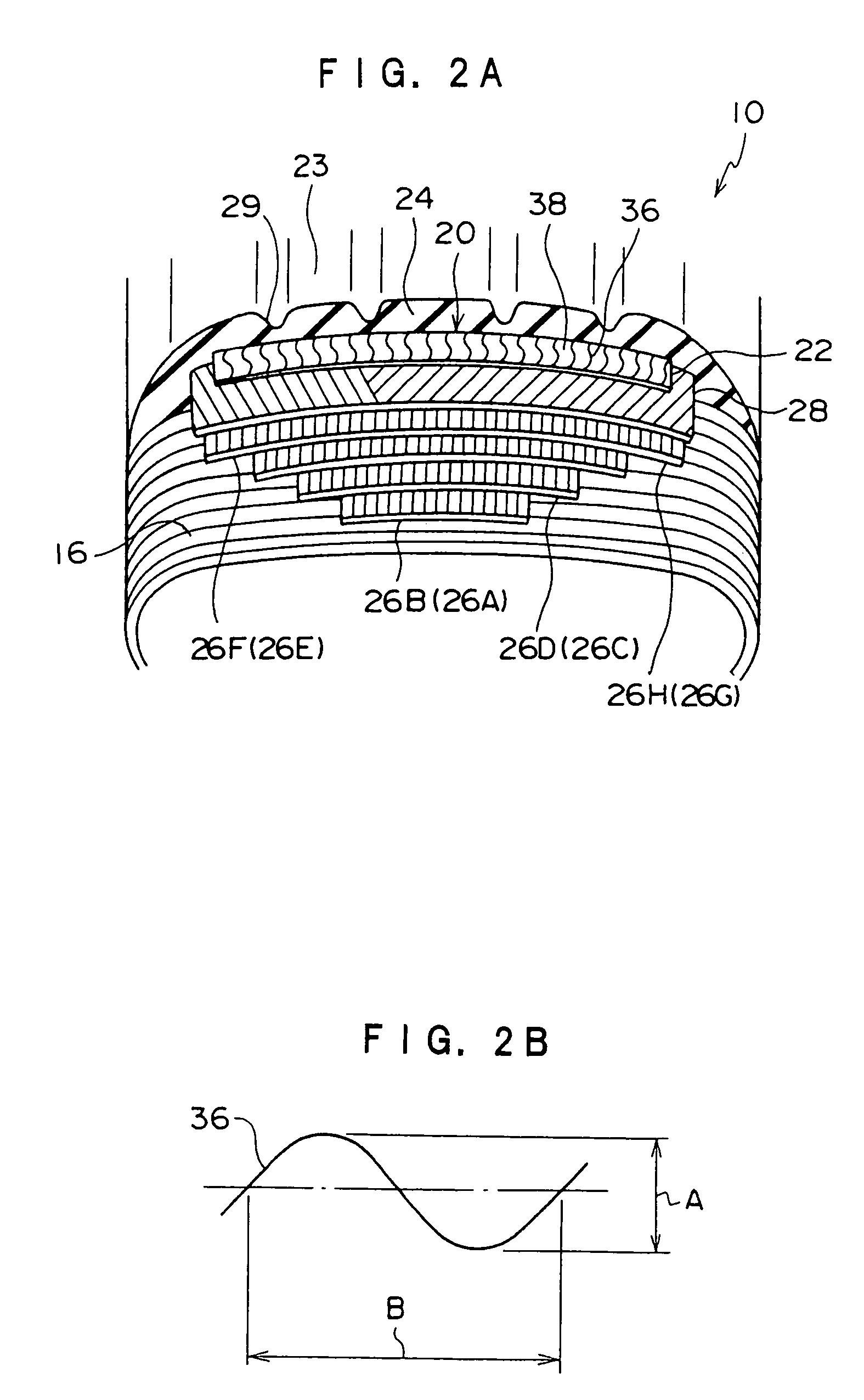
[0222]As shown in FIGS. 1 and 2A, an aircraft pneumatic radial tire 10 (tire size: 1270×455R22 32PR) of the present embodiment has a bead portion 12 which includes bead cores 14 having a circular cross section. A carcass layer 16 including six carcass plies (not shown) in which rubber-coated organic fiber cords are arranged in a radial direction is retained to the bead cores 14.

[0223]Note that, since other structure members such as flipper and chafer are the same as the conventional members, they are not illustrated in the drawings.

[0224]A belt layer 20 is provided on an outer peripheral surface of a crown region located on an outer side of the carcass layer 16 in the radial direction of the tire. A tread rubber layer 24 constituting a tre...

second embodiment

[0314]A pneumatic radial tire 40 of a second embodiment of the invention will be described with reference to FIG. 6. The components same as those of the first embodiment are designated with the same symbols, and explanation thereof is omitted.

[0315]As shown FIG. 6A, in the pneumatic radial tire 40 of the embodiment, the auxiliary belt layer 28 is a so-called intersection belt layer and other structure of the pneumatic radial tire 40 is the same as that of the pneumatic radial tire 10 of the first embodiment.

[0316]As shown in FIG. 6B, the auxiliary belt layer 28 is formed from two belt plies, belt ply 28 B and belt ply 28 C. For example, the belt ply 28B includes a plurality of organic fiber cords diagonally inclined left upwardly with respect to the tire equator surface CL, and the belt ply 28C includes a plurality of organic fiber cords diagonally inclined right upwardly with respect to the tire equator surface CL.

[0317]The organic fiber cords used for the belt ply 28B and the belt...

third embodiment

[0323]Next, a pneumatic radial tire 42 of a third embodiment of the invention will be described with reference to FIG. 7. The components same as those of the first embodiment are designated with the same symbols, and explanation thereof is omitted.

[0324]As shown in FIG. 7, in the pneumatic radial tire 42 of the present embodiment, only the ply structure of the main belt layer 26 and the material of the organic fiber cord are changed, and other structure of the pneumatic radial tire 40 is the same as that of the pneumatic radial tire 10 of the first embodiment.

[0325]The main belt layer 26 of the embodiment is formed of four belt plies, i.e., a first belt ply 26A to a fourth belt ply 26D which are endless zigzag-wound belts having the same structure as that of the belt ply 28A of the auxiliary belt layer 28 used in the first embodiment (the number of plies of the main belt layer 26 is counted as eight).

[0326]The angle of the organic fiber cord in each of the first belt ply 26A to the ...


PUM

PropertyMeasurementUnit
elongation percentageaaaaaaaaaa

Abstract

In the pneumatic radial tire of the present invention, a total strength K0 of a belt layer 20 in a circumferential direction of the tire per unit of width at a tire equator surface position P0 is set greater than a total strength of the belt layer 20 in the circumferential direction of the tire per unit of width at a width position P2 corresponding to ⅔ of a maximum width of the belt layer having the tire equator surface CL as a center.

Description

FIELD OF THE INVENTION[0001]The present invention relates to a pneumatic radial tire and a producing method of the pneumatic radial tire, and more particularly, to a pneumatic radial tire and a producing method of the pneumatic radial tire which are suitable for an aircraft and which can enhance against cutting by foreign matter and the like, and can reduce a weight of the tire.BACKGROUND ART[0002]A conventional pneumatic radial tire, especially an aircraft radial tire has a large swell of a tread surface in its radial direction by a high internal pressure and a centrifugal force caused by high speed rotation.[0003]If the tread surface swells in the radial direction, a tread rubber is expanded in a circumferential direction of the tire.[0004]Generally, the aircraft radial tire is used under conditions of high internal pressure and high load. Therefore, when the tire rides over foreign matter, the aircraft radial tire is poor in properties by which a tread thereof is not damaged when...

Claims


Application Information

Patent Timeline
Patent Type & Authority Patents(United States)
IPC IPC(8): B60C9/08B60C9/18B60C9/20B60C9/22B29D30/10B29D30/70B60C3/00B60C9/26B60C9/28B60C19/00
CPCB29D30/0661B29D30/1628B29D30/70B60C3/00B60C9/20B60C9/22B60C9/263B60C9/28B29D30/10Y10T152/10765B60C2200/02Y10T152/10792Y10T152/10801Y10T152/10783Y10T152/10873D02G3/48D10B2331/02D10B2331/021B60C2009/1871
Inventor YANO, TAKESHIMORI, HIROYUKINAKAMURA, MASAAKIITAI, SEIJI
Owner BRIDGESTONE CORP
Why Eureka
Try Eureka