Thin film magnetic head with thermal flying height control pads located at both ends of all pads series on slider side plane

a slider and thermal flying technology, applied in the field of magnetic head sliders, can solve the problem of inevitably lowering the highest sense current which can be s

Inactive Publication Date: 2010-06-08
WESTERN DIGITAL TECH INC
View PDF10 Cites 2 Cited by
  • Summary
  • Abstract
  • Description
  • Claims
  • Application Information

AI Technical Summary

Benefits of technology

[0008]It is a feature of the present invention to provide a magnetic head slider whose terminal and wiring layout for the heating resistor is improved so as to reduce the influence of the crosstalk current.
[0014]According to the present invention, it is possible to separate the lead wires of the magnetic write element terminals from the lead wires of the magnetic read element terminals by the lead wires of the heating resistor terminals since the heating resistor terminals are respectively located on an outer side or, preferably, on the opposite outer sides of the magnetic write element terminals and magnetic read element terminals. This makes it possible to prevent the write element lead wires from inducing crosstalk current in the read lead wires during write operation.

Problems solved by technology

However, the crosstalk current inevitably lowers the highest sense current which can be set.

Method used


Image

  • Thin film magnetic head with thermal flying height control pads located at both ends of all pads series on slider side plane
  • Thin film magnetic head with thermal flying height control pads located at both ends of all pads series on slider side plane
  • Thin film magnetic head with thermal flying height control pads located at both ends of all pads series on slider side plane

Examples


embodiment 1

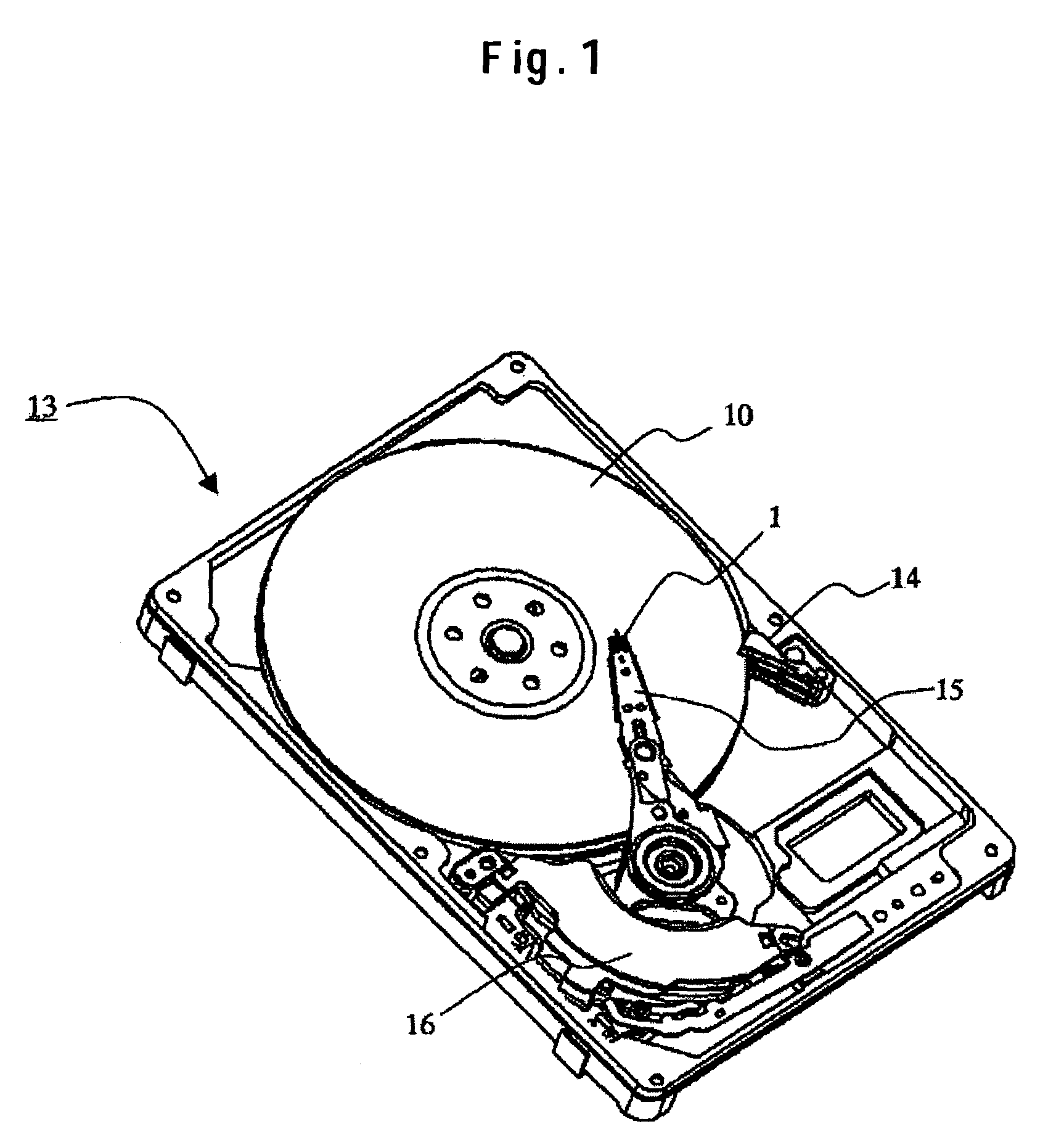
[0026]FIG. 1 schematically shows the configuration of a magnetic disk drive where a slider embodiment is installed. A magnetic disk drive comprises: a magnetic disk 10 which has magnetic information stored thereon and is rotated by a spindle motor; and a slider 1 which is carried and positioned in the radial direction by a load beam 15. Magnetic information is read and written on the magnetic disk while the slider 1 is moving relative to the magnetic disk 10. The slider 1, as a gas-lubricated bearing, is designed to be lifted by the wedge film effect of air so that it does not make direct solid contact with the magnetic disk. To raise the linear recording density, the flying height of the slider is kept within, say, 10 nm.

[0027]The slider 1 is attached to a plate spring-like load beam 15. The load beam gives a load which urges the slider 1 toward the magnetic disk surface. Carried by the load beam 15 which is driven by a voice coil motor 16, the slider 1 performs seek operations in ...

embodiment 2

[0045]FIG. 9 shows another example of the terminal and wiring layout. In this example, the terminals 4 for the magnetic write element, the terminals 5 for the magnetic read element and the terminals 30 for the heating resistor 11 are arranged in this order. That is, the heating resistor 11 terminals 30 are located on the outer side of the magnetic read element terminals 5. In this case, although the magnetic write element wires 33 are separated from the magnetic read element wires 32 by the heating resistor 1 wires 34, vibration characteristics of the suspension may be adversely influenced since the magnetic write element wires 33 and magnetic read element wires 32 causes asymmetry. However, since the wires 32 are separated from the wires 33 by the heating resistor 11 wires 34, it is possible to prevent the write head wires from inducing crosstalk current in the read wires during write operation.

[0046]In FIG. 10, yet another terminal and wiring layout example is shown for comparison...

embodiment 3

[0048]In the aforementioned first embodiment, since the terminals 30 of the heating resistor 11 are located respectively on the outer sides of the other terminals 4 and 5, the lead lines 17 (the wires 34 in FIG. 7) are relatively longer as apparent from FIG. 7. That is, if the material of the lead lines 17 is not so lower in resistivity than the material of the heating resistor 11, the lead lines 17 cause a large heating loss. Thus, in order to heat the heating resistor 11 as effectively as possible, the material of the heating resistor 11 is selected from the highest resistivity ones whereas the material of the lead lines 17 is selected from the lowest resistivity ones.

[0049]Specifically, the heating resistor 11 is made of NiCr or the like whereas the lead lines 17 are made of NiFe, Cu or the like. As a result, the resistance of the heating resistor 11 is at least twice the resistance of the lead lines 17. Thus, it is possible to effectively heat the heating resistor 11, the object...


PUM

PropertyMeasurementUnit
flying heightaaaaaaaaaa
thicknessaaaaaaaaaa
thicknessaaaaaaaaaa

Abstract

Embodiments of the invention prevent the write element lead wires from inducing crosstalk current in the read element lead wires. In one embodiment, a magnetic head slider comprises: a substrate portion; a heating resistor formed on the substrate portion through the intermediary of an insulation layer; a magnetic write element and a magnetic read element which are formed over the heating resistor through the intermediary of an insulation layer; and a terminal array structure provided with first terminals to wire the magnetic write element, second terminals to wire the magnetic read element, and third terminals to wire the heating resistor, wherein two of the third terminals for the heating resistor are located respectively on the opposite outer sides of the first and second terminals. In addition, an arm suspension is provided with a wiring structure in which wires connected to the terminals of the magnetic head slider, wires connected to the terminals, and wires connected to the terminals are guided to a predetermined direction and the magnetic write element lead wires are separated from the magnetic read element lead wires by the wires located in the central portion.

Description

CROSS-REFERENCES TO RELATED APPLICATIONS[0001]This application claims priority from Japanese Patent Application No. JP2004-265013, filed Sep. 13, 2004, the entire disclosure of which is incorporated herein by reference.BACKGROUND OF THE INVENTION[0002]The present invention relates to a magnetic head slider to realize high density recording in a magnetic disk drive. In particular, the invention relates to a thin film magnetic head slider capable of adjusting the distance between the magnetic disk and the magnetic head, a structure to support that magnetic head slider, a magnetic disk drive employing that magnetic head slider and so on.[0003]A magnetic disk drive comprises a rotating magnetic disk and a thin film magnetic head slider (hereinafter referred to as a slider) which is supported and positioned in the radial direction by a load beam. Magnetic information is read / written from / onto the magnetic disk by a read / write element mounted on the slider which runs relatively over the m...

Claims


Application Information

Patent Timeline
Patent Type & Authority Patents(United States)
IPC IPC(8): G11B5/60
CPCG11B5/314G11B5/6064G11B5/6005G11B5/607G11B5/6082
Inventor KATO, ATSUSHISHIRAKI, KIYONORITANABE, MASANORI
Owner WESTERN DIGITAL TECH INC
Why Eureka
Try Eureka