Electro-permanent magnet for power microwave tubes

a permanent magnet and microwave tube technology, applied in the field of microwave tube power, can solve the problems of repulsion and attraction forces, assembly requires massive machines to hold pieces, and no one proposes or even suggests that an unusually powerful through-bore field can be produced, etc., and achieves the effect of high magnetic flux density and sufficient siz

Inactive Publication Date: 2010-07-27
BARNETT LARRY R
View PDF12 Cites 5 Cited by
  • Summary
  • Abstract
  • Description
  • Claims
  • Application Information

AI Technical Summary

Benefits of technology

[0019]A magnet configuration for a power microwave tube with a resonant cavity comprises a permanent magnet with an axis-aligned through-bore of sufficient size to contain the resonant cavity. The magnet configuration produces a very high magnetic flux density within the through-bore. The permanent magnet has an inner chamber that is centered on the axis with opposite magnet poles aligned along the axis. The magnet configuration further comprises an electromagnet coil fitting in the chamber and encircling the axis such that the coil produces a magnetic field that reinforces the magnetic field along the axis from the permanent magnet. An optional protrusion spanning the through-bore narrows an air gap between the poles. The method provides a magnetic field in a power microwave generator by combining a permanent magnet with an electromagnet in accordance with the magnet configuration and energizes the electromagnetic coil with a constant or pulsing coil current.

Problems solved by technology

None proposes, or even suggests, that an unusually powerful through-bore field can be produced by using both a permanent magnet and an electromagnet in an optimal way.
In comparison, magnets in conventional systems are usually precharged and can often have repulsion and attraction forces approaching many tons.
Thus, assembly requires massive machines to hold the pieces while being put together and clamped in place.
It is often dangerous because the forces can expel pieces at high velocities.

Method used


Image

  • Electro-permanent magnet for power microwave tubes
  • Electro-permanent magnet for power microwave tubes
  • Electro-permanent magnet for power microwave tubes

Examples


Embodiment Construction

[0026]In the following description, reference is made to the accompanying drawings, which form a part hereof and which illustrate several embodiments of the present invention. The drawings and the preferred embodiments of the invention are presented with the understanding that the present invention is susceptible of embodiments in many different forms and, therefore, other embodiments may be utilized and structural and operational changes may be made without departing from the scope of the present invention.

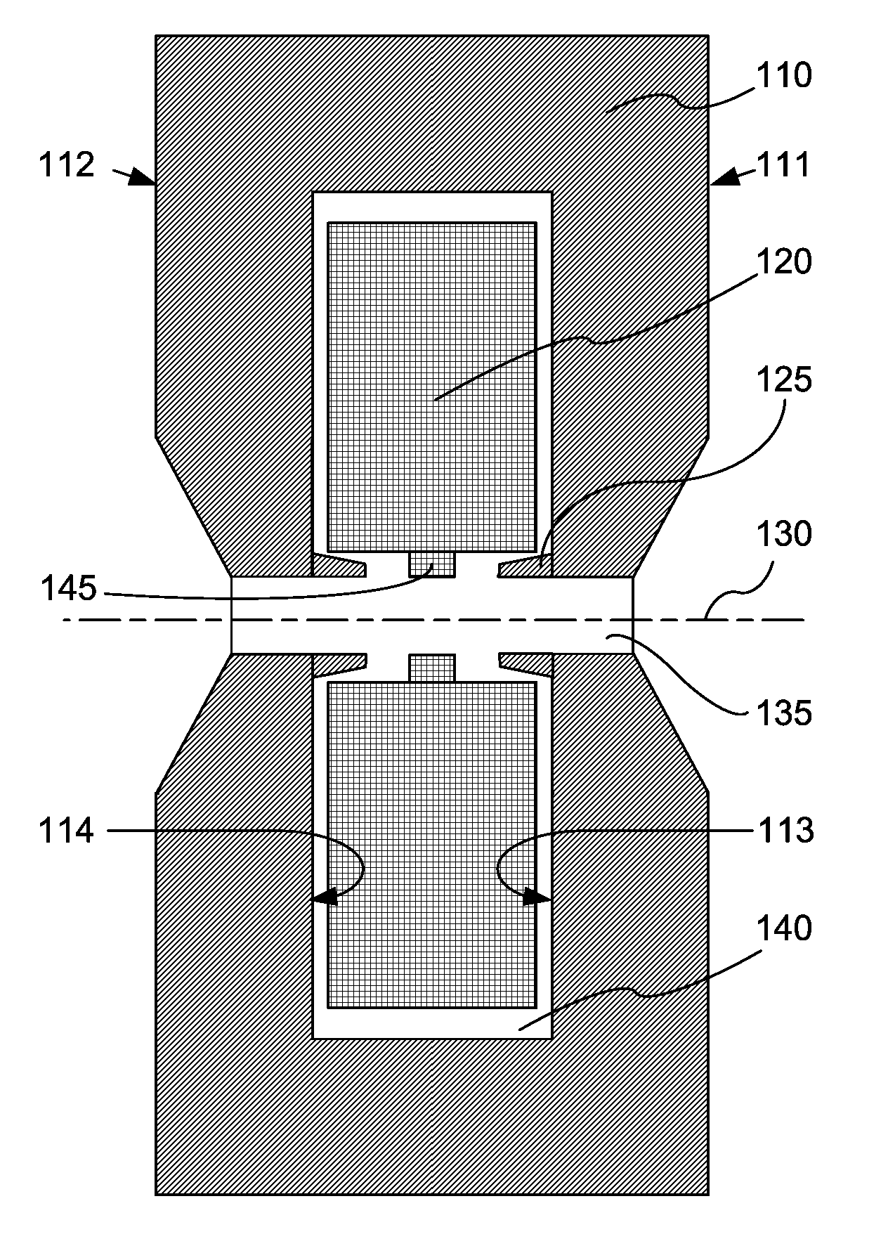
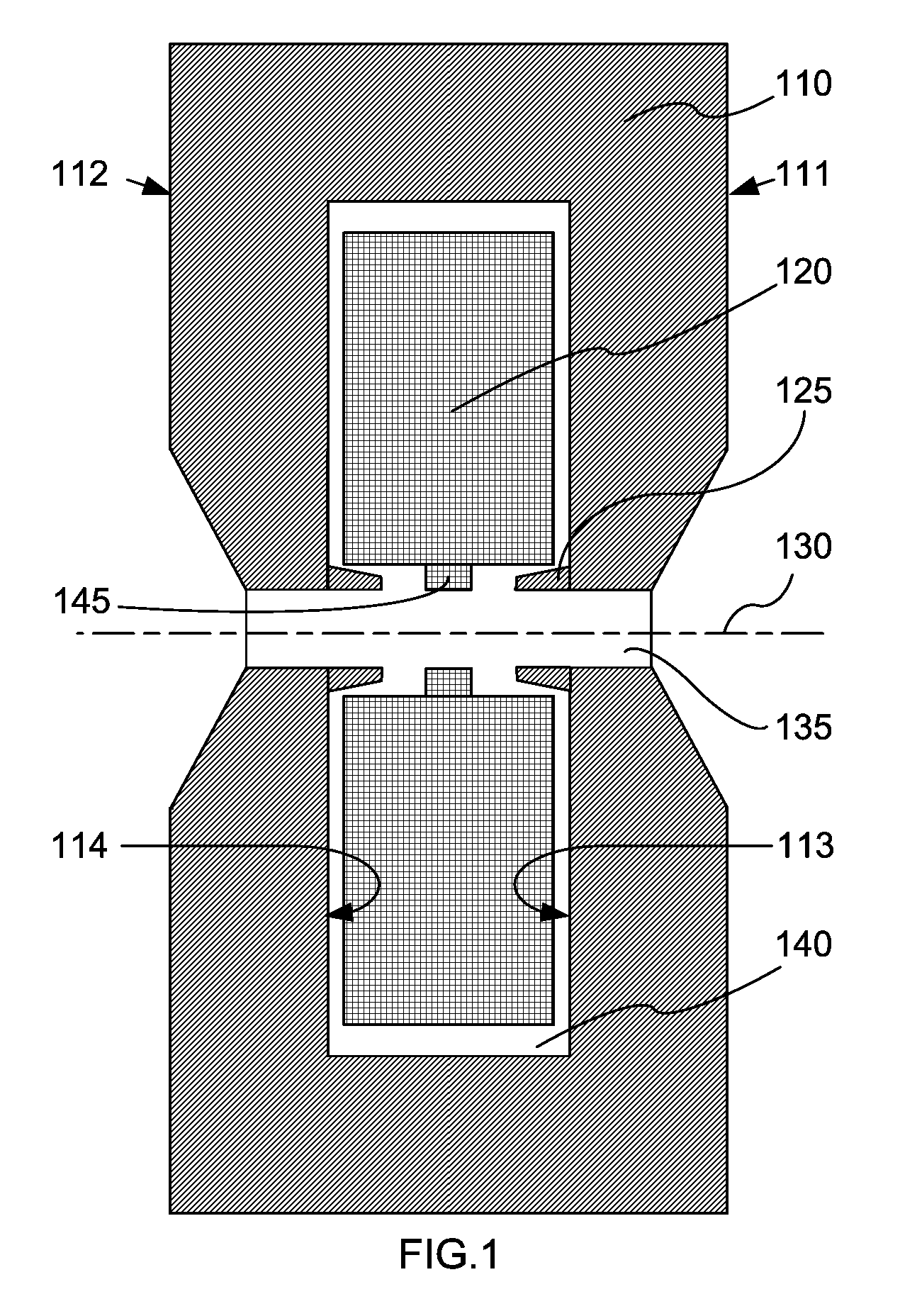
[0027]FIG. 1 is an illustration of an embodiment of the invention in a configuration for a gyrotron. It is a cross-sectional view of this embodiment in the configuration for a power microwave tube having a resonant cavity.

[0028]Correspondingly, FIG. 3 plots the magnetic flux density, B, in Teslas on the vertical axis against millimeters of this embodiment.

[0029]The electropermagnet design and flux density plot are based on a calculation (using the MAXWELL software by ANSOFT CORPO...


PUM


Abstract

A magnet configuration for a power microwave tube with a resonant cavity comprises a permanent magnet (110) with an axis-aligned through-bore (135) of sufficient size to contain the resonant cavity. The permanent magnet has an inner chamber (140) that is centered on the axis (130) with opposite magnet poles aligned along the axis. The magnet configuration further comprises an electromagnet coil (120) fitting in the chamber and encircling the axis such that the coil produces a magnetic field that reinforces the magnetic field from the permanent magnet. An optional protrusion (125) spanning the through-bore narrows an air gap between the poles. The method provides a magnetic field in a power microwave generator by combining a permanent magnet with an electromagnet in accordance with the magnet configuration and energizes the electromagnetic coil, which may be by pulsing the coil current.

Description

CROSS-REFERENCE TO RELATED APPLICATION[0001]The present invention claims the benefit of the filing date of prior U.S. provisional application 60 / 807,849 filed 20 Jul. 2006, the text of which is included by reference herein.FIELD OF INVENTION[0002]In the field of power microwave tubes, a combination permanent magnet and electromagnet in a configuration that produces a through-bore magnetic field significantly greater than the fields from similar individual magnets.BACKGROUND OF THE INVENTION[0003]Power microwave tubes use magnetic flux to emit microwave radiation. The invention has application in magnets for gyrotron, peniotron tubes and other types of high frequency microwave tubes that require very high magnetic fields, such as millimeter and submillimeter wave traveling-wave tubes, backward wave oscillators, carcinotrons, and others. In this application, reference to “power microwave tubes” is intended to be broadly defined to include: (1) high frequency microwave tubes of varying...

Claims


Application Information

Patent Timeline
Patent Type & Authority Patents(United States)
IPC IPC(8): H01J23/08
CPCH01F7/0278H01F7/202H01J23/10H01J25/025
Inventor BARNETT, LARRY R.
Owner BARNETT LARRY R
Why Eureka
Try Eureka