Filament winding apparatus

a technology of winding apparatus and filament, which is applied in the manufacture of coils, inductance/transformers/magnets, transportation and packaging, etc., can solve the problems of large amount of time, inefficient formation of pressure containers, and very limited displacement amount of exit guides and feed eyes, so as to achieve easy shifting, high quality reinforcement layers, and simplified peripheral structures of guide tubes

Active Publication Date: 2010-10-19
MURATA MASCH LTD
View PDF16 Cites 41 Cited by
  • Summary
  • Abstract
  • Description
  • Claims
  • Application Information

AI Technical Summary

Benefits of technology

[0009]The present invention provides a filament winding apparatus that efficiently performs a winding process of a fiber bundle with respect to a mandrel in a short period of time, and orderly performs the winding of the fiber with respect to a dome part of the mandrel with the supply position of the fiber bundle changed between cylindrical and dome parts of the mandrel.
[0014]In the present invention, the helical winding head is configured by the guide ring, the group of guide tubes arranged in the circumferential direction of the guide ring and the tube operation mechanism that reciprocates the guide tube, and the winding process is performed while simultaneously supplying the group of fiber bundles to the mandrel. When the guide tube is facing the dome part of the mandrel, the guide tube is operated by the tube operation mechanism to move closer to the circumferential surface of the dome part and to supply the fiber bundle in the vicinity of the circumferential surface of the dome part. Thus, when the guide tube is moved closer and the fiber bundle is supplied in the vicinity of the circumferential surface of the dome part, the distance between the winding position of the fiber bundle and the guide tube at the dome part is reduced, and thus the fiber bundle can be orderly wound according to an appropriate winding trajectory. Therefore, according to the filament winding apparatus of the present invention, the winding of the fiber bundle with respect to the dome part is efficiently performed in an orderly fashion and a high quality reinforcement layer is formed.
[0015]The guide tube can be projected and retreated while matching the change in shape of the dome part of the mandrel by setting the movement trajectory of the guide tube when being operated with the tube operation mechanism to move closer to the curved line form along the outer contour line of the dome part of the mandrel. The spacing between the guide tube and the dome part is always set constant, such that the winding process of the fiber bundle at the dome part is further appropriately performed. By contrast, if the movement trajectory of the guide tube is changed to a linear form, the spacing between the guide tube and the dome part continuously changes, and the winding position of the fiber bundles tends to easily shift.
[0016]The peripheral structure of the guide tube can be simplified while avoiding concentrated arrangement of equipment at the periphery of the guide tube by supporting the tube holder, which is integral with the guide tube, in a freely sliding manner by the guide groove of the guide ring, and arranging the tube operation mechanism between the fixed frame and the tube holder. For instance, the peripheral structure of the guide tube can be simplified and the concentration of equipment inhibited by arranging the tube operation mechanism in a dispersed manner using the surface wall of the fixed frame. If the peripheral structure of the guide tube is simplified, tasks such as setting and replacing of the fiber bundle can be easily performed without being disturbed by the equipment.

Problems solved by technology

In either case, the displacement amount of the exit guide and the feed eye is very limited.
Thus, forming a reinforcement layer by repeatedly performing hoop winding and helical winding requires a great amount of time, and the pressure container is thereby not efficiently formed.
Thus, it becomes difficult to orderly wind the group of fiber bundles around the dome part.

Method used


Image

  • Filament winding apparatus
  • Filament winding apparatus
  • Filament winding apparatus

Examples


example

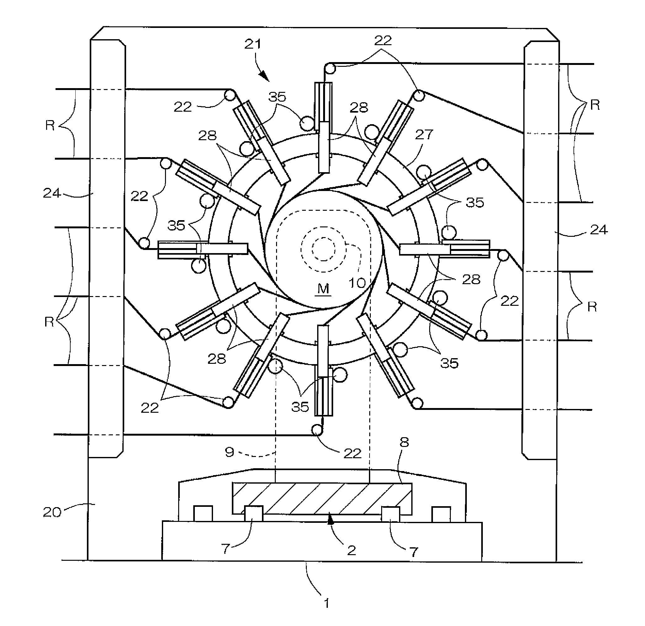
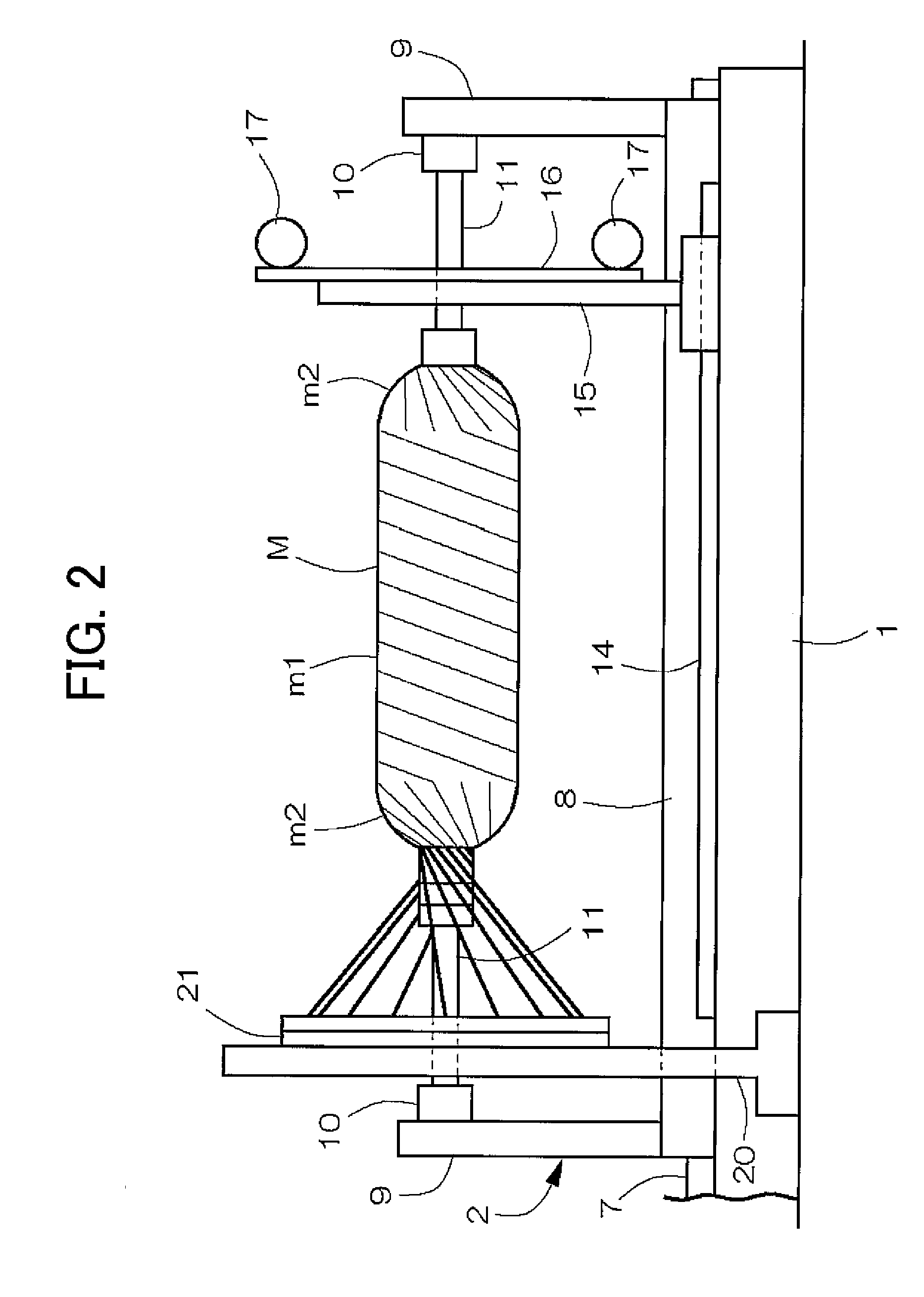
[0030]FIGS. 1-9 show an example of a filament winding apparatus (hereinafter simply referred to as a winding apparatus) according to the present invention. In FIGS. 2 and 3, the winding apparatus is configured by a fiber bundle supply structure and a winding device. The winding device comprises a supporting board 2 that is arranged on an upper part of a mount 1 that is long in a left and right direction and that supports a mandrel M; a hoop winding device; a helical winding device; and a mandrel replacing device. The supporting board 2 and the hoop winding device are driven by a drive mechanism in a reciprocating manner along a longitudinal direction of the mount 1. The helical winding device is arranged at a central position of the mount 1, and feeds and guides a fiber bundle R from a group of creels supported by the fiber bundle supply structure to the mandrel M.

[0031]The mandrel M, in a case where the final product is a pressure container, is a metal container including high stre...


PUM

PropertyMeasurementUnit
movementaaaaaaaaaa
diameteraaaaaaaaaa
rotational poweraaaaaaaaaa

Abstract

A filament winding apparatus that efficiently and orderly winds a fiber bundle with respect to a mandrel in a short period of time. A supporting board supports the mandrel, and a helical winding head supplies and guides the fiber bundle towards the mandrel. The helical winding head includes a group of guide tubes radially arranged on a circumferential surface of a guide ring, and a tube operation mechanism that reciprocates the guide tube along a tube axis center direction. The guide tube is moved closer to a circumferential surface of the dome part when the guide tube is facing a dome part of the mandrel such that the distance between the winding position of the fiber bundle and the guide tube at the dome part can be reduced, and the fiber bundle is orderly wound according to an appropriate winding trajectory.

Description

CROSS-REFERENCE TO RELATED APPLICATIONS[0001]This application claims the benefit of priority under 35 USC 119 of Japanese application no. 2007-296693, filed on Nov. 15, 2007, which is incorporated herein by reference.BACKGROUND OF THE INVENTION[0002]1. Field of the Invention[0003]The present invention relates to a filament winding apparatus equipped with a helical winding device, and a modified form of a supply structure of a fiber bundle configured by a guide ring and a guide tube arranged in a ring thereof.[0004]2. Description of the Related Art[0005]A pressure container is formed through a filament winding method by a reinforcement layer wound around a circumferential surface of a hollow mandrel. In most cases, the mandrel integrally includes a middle cylindrical part continuing to dome parts at both left and right ends of the cylindrical part. A fiber bundle is wound around the cylindrical part and the left and right dome parts to form the reinforcement layer. The fiber bundle i...

Claims


Application Information

Patent Timeline
Patent Type & Authority Patents(United States)
IPC IPC(8): B21C47/02
CPCB29C53/602B29C53/8016B29C53/66
Inventor UOZUMI, TADASHITANIGAWA, MOTOHIRO
Owner MURATA MASCH LTD
Why Eureka
Try Eureka